Power compensation circuit of LED lamp
A LED lamp and power compensation technology, applied in the field of LED applications, can solve the problems of high price, change, and increased cost, and achieve good consistency
- Summary
- Abstract
- Description
- Claims
- Application Information
AI Technical Summary
Problems solved by technology
Method used
Image
Examples
Embodiment 1
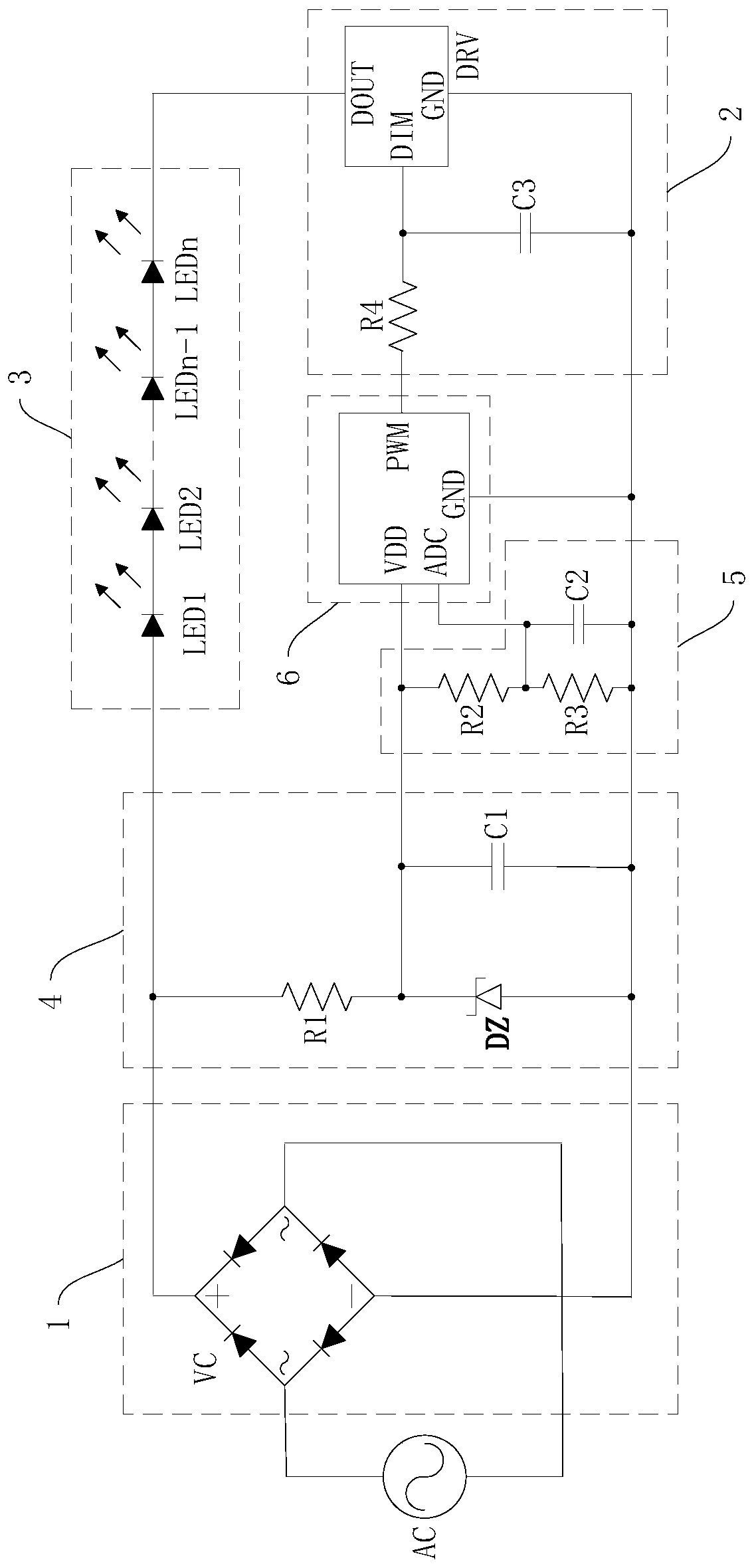
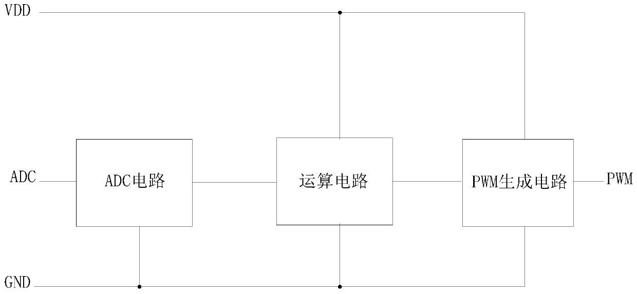
[0028] Embodiment 1: As shown in the figure, a power compensation circuit for LED lights includes a rectifier module 1, a constant current drive module 2, an LED light string 3, a low-voltage DC power supply module 4, an acquisition module 5 and a control system with a preset algorithm Module 6, the rectifier module 1 is used to convert high-voltage alternating current into line voltage and output it; the constant current drive module 2 is used to adjust the current value of the LED light string 3; the low-voltage DC power supply module 4 is used to convert the line voltage output by the rectifier module 1 It is a low-voltage direct current; the acquisition module 5 is used to collect the low-voltage direct current output by the low-voltage direct current power supply module 4, and outputs an analog sampling signal; the control module 6 is used to receive the analog sampling signal output by the acquisition module 5, and convert the analog sampling signal into a digital signal ...
Embodiment 2
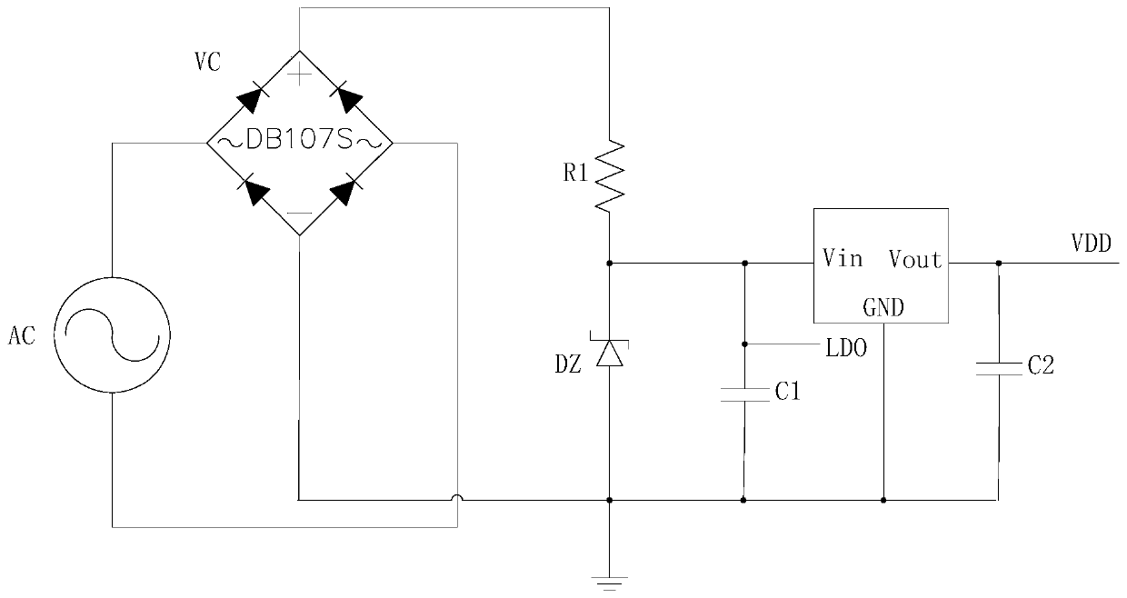
[0031]Embodiment 2: the rest is the same as Embodiment 1, the difference is that the rectifier module 1 is a rectifier bridge VC, the low-voltage DC power supply module 4 includes a first resistor R1, a Zener diode DZ and a first capacitor C1, and the acquisition module 5 includes The second resistor R2, the third resistor R3 and the second capacitor C2, the control module 6 adopts a control chip of the model PFC232, the control chip is provided with VDD pins, ADC pins, PWM pins and GND pins, constant current The drive module 2 includes a fourth resistor R4, a third capacitor C3 and a constant current driver chip DRV. The constant current driver chip DRV is provided with a DIM analog dimming interface, a DOUT pin and a GND pin, and two AC inputs of the rectifier bridge VC The ends are respectively connected to the high-voltage alternating current AC, the positive pole of the rectifier bridge VC, one end of the first resistor R1 and the positive pole of the LED light string 3 ar...
Embodiment 3
[0035] Embodiment three: the remaining parts are the same as embodiment two, the difference is that the preset algorithm of the control module 6 is as follows
[0036] A=(refA / samA)*duty
[0037] Among them, A is the dimming data, refA is the sampling value of the ADC sampling signal corresponding to the minimum stable voltage value of the Zener diode DZ after filtering, samA is the sampling value, and duty is the duty cycle base corresponding to refA.
PUM
 Abstract
Description
Claims
Application Information
 - R&D
- Intellectual Property
- Life Sciences
- Materials
- Tech Scout
- Unparalleled Data Quality
- Higher Quality Content
- 60% Fewer Hallucinations
Browse by: Latest US Patents, China's latest patents, Technical Efficacy Thesaurus, Application Domain, Technology Topic, Popular Technical Reports.
© 2025 PatSnap. All rights reserved.Legal|Privacy policy|Modern Slavery Act Transparency Statement|Sitemap|About US| Contact US: help@patsnap.com


