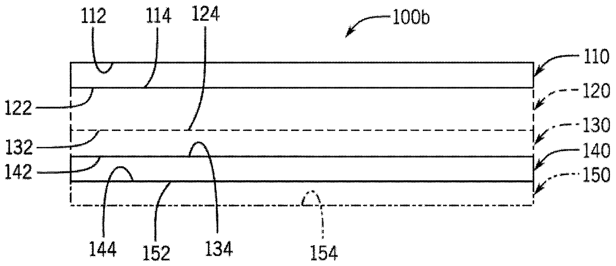
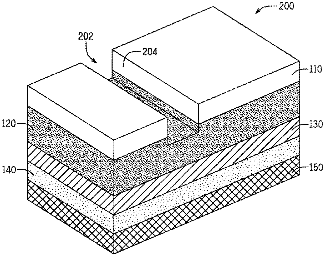
Label construction for ablative laser marking
A label, face surface technology applied in the field of label structures for ablative laser marking, which can solve the problem of significant risk to the performance or quality of the final product, and the loss of readability of ablated labels
- Summary
- Abstract
- Description
- Claims
- Application Information
AI Technical Summary
Problems solved by technology
Method used
Image
Examples
Embodiment
[0134] The following examples illustrate in detail the manner in which the tags described herein can be used or implemented and will enable those skilled in the art to more readily understand the principles thereof. The following embodiments are provided by way of illustration and are not meant to be limiting in any way.
[0135] The following examples illustrate how adjusting the layer thicknesses of the topcoat and sacrificial layers (even if the composition of the layers is otherwise similar) can lead to significant differences in chip generation. where, assuming the topcoat has been designed enough to allow the laser to pass through it to the sacrificial layer, with a thicker sacrificial layer, more material will volatilize in the sacrificial layer, thus improving the topcoat during ablation layer removal. Additionally, there can be advantages associated with having a thicker sacrificial layer—even if the topcoat thickness is also somewhat increased—because there is a gre...
Embodiment I
[0139] Use from 50 W CO 2 The 36% power of the laser machine ablated each of the first sample of the first comparative label and the first sample of the second comparative label. The ablated area of each label is generally square. Figures 8A-8C with Figures 9A-9B Laser ablated first and second contrast labels are shown, respectively.
[0140] Figures 8A-8C shows the ablated first contrast label, Figure 8B with 8C A portion of the non-ablated area and the ablated area are shown at 50X magnification, respectively. exist Figure 8B , can be seen as fragments of dark areas on a light background, while in Figure 8C , can be seen as fragments of light areas on a dark background. The readability of the first comparison label, especially at smaller print sizes, is impaired by the formation of fragments.
[0141] Figures 9A-9B show the ablated second contrast label, and Figure 9B The ablated area at 5Ox magnification is shown. Figure 9B to Figure 8C The comparison...
Embodiment II
[0143] For further illustration of the fragments formed, as described above, using 2 A second sample of the first comparative label and a second sample of the second comparative label were ablated at 36% power of the laser machine. The ablated area of each label is typically a barcode-like pattern. Figure 10A with Figure 11A The ablated areas of the second sample of the first comparative label and the second sample of the second comparative label are shown, respectively. After ablation, a piece of clear Scotch tape was placed over the ablated area of the second sample of the first comparative label and the second sample of the second comparative label such that the adhesive side of the tape was aligned with the corresponding label. Make physical contact with the ablated area. The tape was then removed and fixed to a white substrate to determine the size of the debris attached to the tape.
[0144] Figure 10B with Figure 11B The tape test results are shown for a s...
PUM
| Property | Measurement | Unit |
|---|---|---|
| size | aaaaa | aaaaa |
| size | aaaaa | aaaaa |
| size | aaaaa | aaaaa |
Abstract
Description
Claims
Application Information
 - R&D
- Intellectual Property
- Life Sciences
- Materials
- Tech Scout
- Unparalleled Data Quality
- Higher Quality Content
- 60% Fewer Hallucinations
Browse by: Latest US Patents, China's latest patents, Technical Efficacy Thesaurus, Application Domain, Technology Topic, Popular Technical Reports.
© 2025 PatSnap. All rights reserved.Legal|Privacy policy|Modern Slavery Act Transparency Statement|Sitemap|About US| Contact US: help@patsnap.com


