
Body position fixator for pediatric surgical operation

A surgical operation and fixator technology, applied in the field of medical appliances, to achieve the effects of high elasticity and flexibility, reducing position adjustment and reducing secondary injuries

Inactive Publication Date: 2019-12-10
THE AFFILIATED HOSPITAL OF QINGDAO UNIV
View PDF0 Cites 2 Cited by
  • Summary
  • Abstract
  • Description
  • Claims
  • Application Information

AI Technical Summary

Problems solved by technology

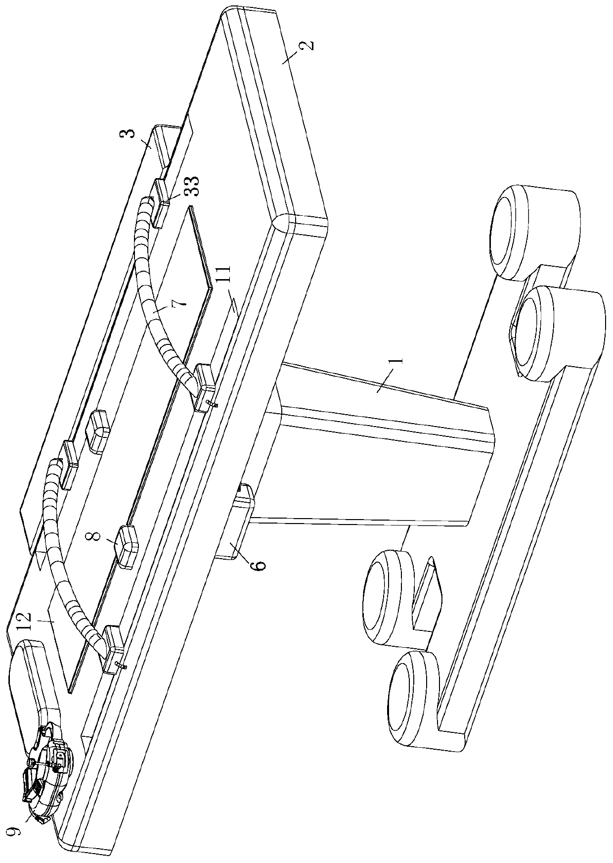
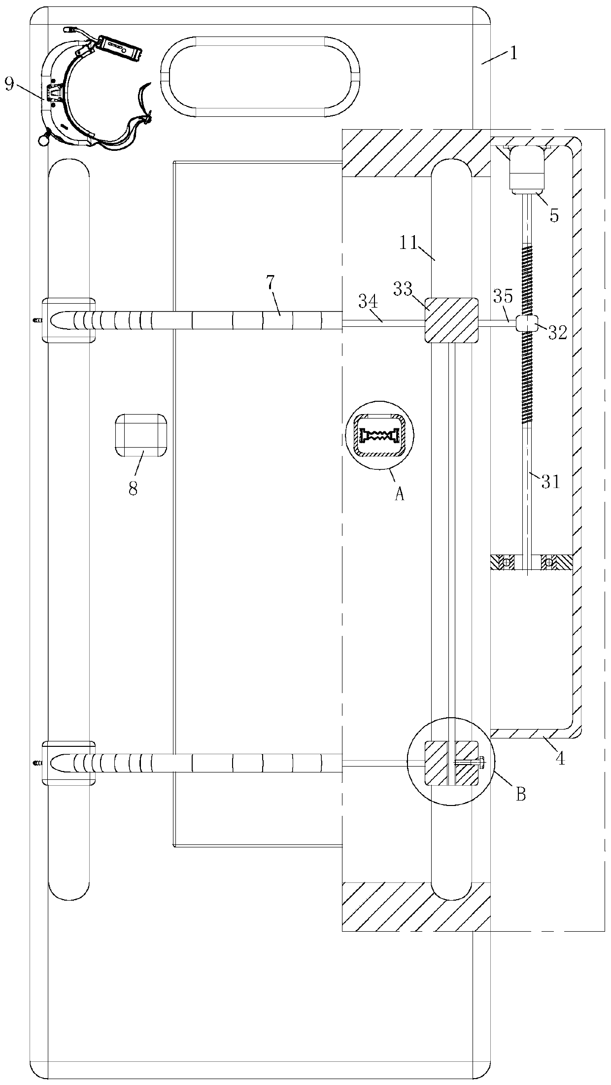
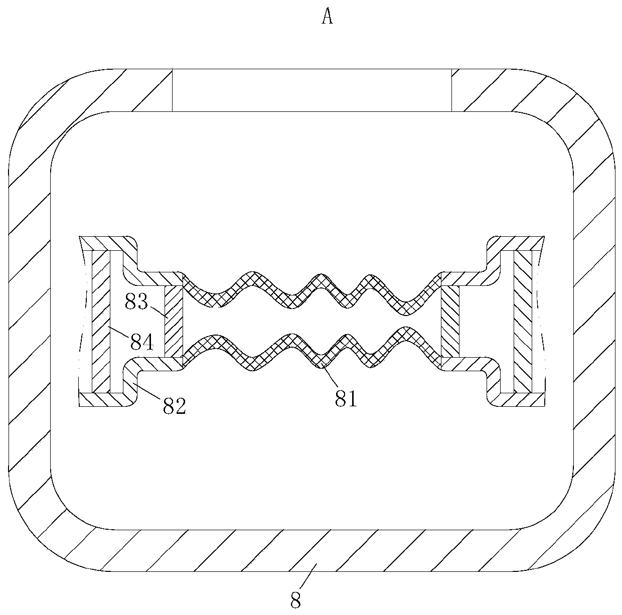
[0006] The technical solution adopted by the present invention to solve the technical problem is: a child surgical position fixer, including a support platform and a support frame, the support platform is located on the top of the support frame; a fixing module is provided on the support platform, and the The fixed module includes a housing, a motor, an air pump and a locking airbag. The housing is installed on the right side of the support platform. The motor is installed inside the housing. The bottom of the motor is connected to a rotating shaft, and the middle of the rotating shaft is set as a ball wire The form of a rod, and the outer surface of the ball screw is connected with a screw sleeve; a set of chute is symmetrically arranged on the table of the support table, and two pairs of slide plates are symmetrically installed in the chute, and the adjacent two slide plates They are all connected by connecting rods, and at the same time, the slide plate on the top of the right chute is connected with the screw sleeve by a draw bar. There is an arc-shaped locking airbag between the two symmetrical slide plates in the chute, and the support platform There is a group of air pumps on the left side of the body, the air pumps are all connected to the left end of the locking air bag, the right end of the locking air bag is clamped on the outer surface of the slide plate, and a controller is installed in the housing. The above-mentioned controller is used to control the automatic operation of the device; when working, when the child patient is lying on the operating table, the right end of the locking airbag is clamped on the outer surface of the slide plate, and at this time the controller controls the motor to run, and the motor drives the bottom when it is running. The rotating shaft rotates so that the rotating shaft drives the screw sleeve on the surface to slide through the ball screw set in the middle. The two slides are connected by a connecting rod, so that when the draw bar moves, the two pairs of slides connected to each other slide synchronously in the chute, thereby driving the locking airbags installed on the slides to move synchronously, so that the locking airbags can For children of different sizes, the position can be adjusted quickly according to the size of the children, which more conveniently and quickly plays the role of fixing the surgical position; and when the sliding plate drives the locking airbag to complete the positioning of the fixed position, the controller controls the air pump to start When the air pump works, the connected locking airbag is inflated, so that the gas in the locking airbag increases in volume and expands. When the locking airbag expands, it squeezes the child patient inside until the locking airbag expands to the distance between the patient's body The space is in a tight state, so as to play a role in fixing children in surgery; the beneficial effect of adopting this invention is: by changing the bandage fixing method of the traditional operation to the locking air bag fixing method, on the one hand, the traditional body position is reduced. It is inconvenient to adjust the position during fixation. On the one hand, the locking airbag used for body position fixation has higher controllability, which can conveniently and quickly adjust the tightness of the body position fixation, and the locking airbag has higher elasticity. And flexibility, reduce the secondary injury caused by high hardness bandages for children patients, so as to provide more effective protection for children patients

Method used


Image

  • Body position fixator for pediatric surgical operation
  • Body position fixator for pediatric surgical operation
  • Body position fixator for pediatric surgical operation

Examples


Embodiment approach

[0023] As an embodiment of the present invention, the sliding plate 33 at the bottom of the chute 11 is provided with a positioning hole 331, the bottom end of the connecting rod 34 is located in the positioning hole 331, and a positioning bolt is provided on one side of the positioning hole 331. 36, the positioning bolt 36 is used to fix the bottom end of the connecting rod 34; during work, when performing operations on different body positions for children with different body types, it is necessary to adjust the relative position of the locking airbag 7, and the integrated arrangement The sliding plate 33 makes it difficult to change the relative position of the locking airbag 7 during the movement. At this time, the positioning bolt 36 is screwed to unscrew it, so that the end of the positioning bolt 36 no longer squeezes and fixes the bottom end of the connecting rod 34. Push slide plate 33 this moment and make it slide on connecting rod 34, after being adjusted to suitable...


PUM


Abstract

The invention belongs to the technical field of medical appliances, in particular to a body position fixator for pediatric surgical operation. The body position fixator comprises a supporting platformand a supporting frame. A bandage fixation mode of traditional operation is changed into a locking air bag fixation mode, on one hand, the problem that the position adjustment is inconvenient duringtraditional body position fixing is solved, on the other hand, a locking air bag has higher elasticity and flexibility, secondary injury to a patient due to too tight fixation by a high-hardness bandage is reduced, and therefore, the child patient is effectively protected; besides, fixed boxes are arranged on the supporting platform, and by cooperation of extrusion air bags, No.1 pistons and No.2pistons in the fixed boxes, the locking fixation effect of the locking air bag on the patient is enhanced and unsmooth operation caused by body movement when the patient is nervous or painful is reduced.

Description

technical field [0001] The invention belongs to the technical field of medical appliances, in particular to a body position fixer for children's surgical operation. Background technique [0002] When a child patient undergoes surgery, it is necessary to fix the patient's position according to the surgical site, so that the patient can fully expose the surgical field of view and facilitate the smooth operation. If the patient's position is improper, it will cause unnecessary damage to the patient, especially to the side of the patient. When debridement, surgery or suture are performed on the body, it is difficult to maintain a consistent position. Generally, it is necessary to temporarily block the patient's body or be supported by medical staff. The patient's body is unstable throughout the process, and the requirements for medical staff are relatively high, making the work difficult. , It is more difficult to fix the position of pediatric patients. Due to the hyperactivity ...

Claims


Application Information

Patent Timeline
Patent Type & Authority Applications(China)
IPC IPC(8): A61G13/12A61B90/14
CPCA61B90/14A61G13/1265
Inventor 刘玉圣
Owner THE AFFILIATED HOSPITAL OF QINGDAO UNIV
Learn More