Chipping machine for producing oriented strand boards on basis of plant stems

An oriented strand board and plant stem technology, which is applied in the manufacture of thin wood chips, wood processing appliances, manufacturing tools, etc., can solve the problems of slow discharge speed, poor chipping effect, matching feeding speed, etc., to improve uniformity. , Improve production efficiency and avoid the effect of stuck

Pending Publication Date: 2019-12-10
安乡汉创新材料科技有限公司
View PDF0 Cites 0 Cited by
  • Summary
  • Abstract
  • Description
  • Claims
  • Application Information

AI Technical Summary

Problems solved by technology

[0003] The existing particleboard pretreatment process first uses a chipper to cut into irregular blocks, and then flakes through a planer. The raw material of the traditional OSB is wood with a larger diameter, and for plant stems with a smaller diameter, if Using the traditional particleboard process, it will become irregular broken bodies after entering the chipper, and it will not be able to produce flake materials suitable for making oriented strandboard after entering the chipper
[0004] At present, for chipping equipment for irregular materials, the material is fed radially, and the chips are chipped at the discharge port by means of guillotine, rotary cutting or sawing; due to the irregular length and shape of the stems of plants such as straw, the use of When this kind of equipment is chipping, some plant stems may fall from the discharge port before touching the cutter, the chipping effect is poor, and the segment length is uneven; in addition, the output speed of this kind of chipping equipment is relatively slow , which is far from matching the feeding speed, and because the plant stems have a certain degree of toughness, it often causes the chipping equipment to be stuck, which not only shortens the service life of the equipment, but also further slows down the chipping efficiency

Method used


Image

  • Chipping machine for producing oriented strand boards on basis of plant stems
  • Chipping machine for producing oriented strand boards on basis of plant stems
  • Chipping machine for producing oriented strand boards on basis of plant stems

Examples


Embodiment 1

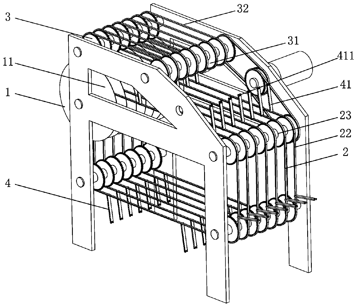
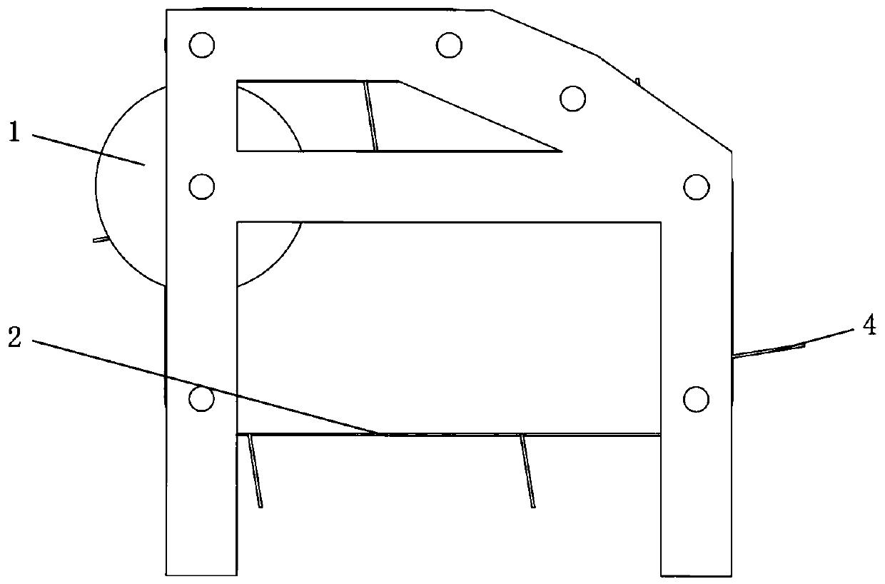
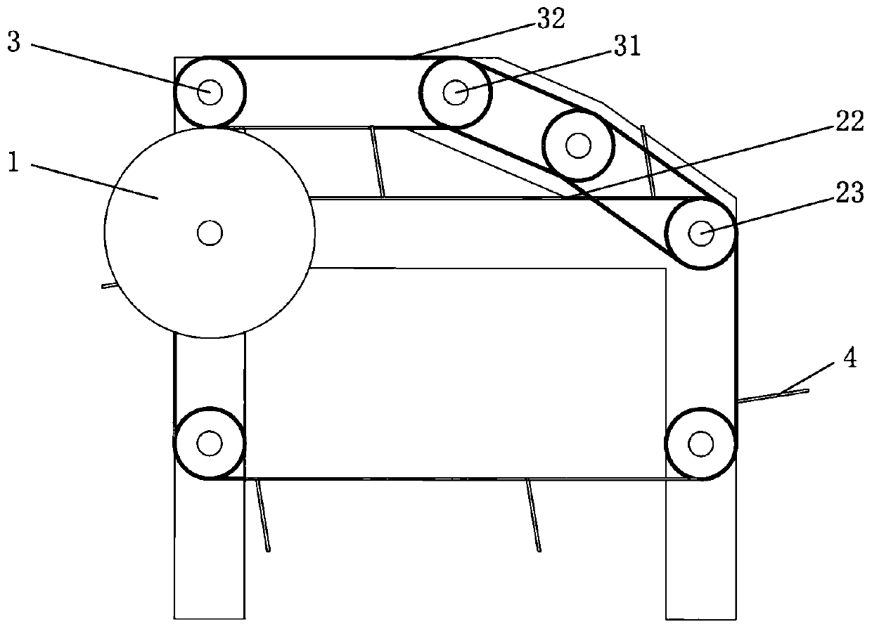
[0044] like Figure 1 to Figure 3 Shown, the chipper that produces oriented strand board based on plant stem bar of the present embodiment comprises:

[0045] The chipping knife set 1 is composed of a plurality of rotating blades 11 distributed axially at intervals along the rotating shaft;

[0046] The feeding device 2 is used to drive the material to be cut to move toward the chipping knife set 1;

[0047] The blocking device 3 is arranged above the feeding device 2, and is used to compress the material when cutting the material;

[0048] And a plurality of pusher plate groups 4 that are distributed in a comb-like shape and can pass between the rotating blades 11;

[0049] One end of each pusher plate 41 in the pusher plate group 4 is fixed on the feeder 2, and the other end moves to the bottom of the stopper 3 with the feeder 2 to form a clamping connection with the stopper 3. During the movement of the knife group 1, the pusher plate 41 and the stopper device 3 always m...

Embodiment 2

[0056] This embodiment is basically the same as Embodiment 1, the only difference is that this embodiment is such as Figure 5 As shown, the clamping groove 411 is a through groove with an opening facing the material retaining chain 32 arranged along the laying direction of the retaining chain 32, and the width of the retaining groove 411 is greater than the width of the chain plate of the retaining chain 32 and less than the pin length of the retaining chain 32 . When the pushing plate 41 moves to the bottom of the material blocking device 3, the opening of the slot 411 is automatically locked into the chain plate of the material blocking chain 32, and the material will apply a thrust force to the pushing plate 41 in a direction opposite to the feeding direction. , and because the width of the slot 411 is smaller than the length of the pin shaft of the retaining chain 32, it will not be turned outward by the thrust, but will always remain in the clamping state until the feedi...

Embodiment 3

[0058] This embodiment is basically the same as Embodiment 1 and Embodiment 2, the difference is: the feeding device 2 of this embodiment is as Image 6 As shown, it includes a plurality of feed holding bars 21 that are horizontal and distributed in a comb-like shape and can pass between the rotating blades 11, and each feed holding bar 21 is provided with a pushing plate 41; The material holder bar 21 reciprocates along the direction perpendicular to the axial direction of the chipping knife set 1 , and can feed material without interfering with the rotating blade 11 . The feeding support bars 21 in this embodiment are fixedly connected at the ends and driven synchronously by a single driving member, which is beneficial to the synchronization of feeding and can also save driving energy. In other implementation manners, it is also possible to adopt a manner in which each feeding support bar 21 is individually driven, and details are not described here.


PUM


Abstract

The invention provides a chipping machine for producing oriented strand boards on the basis of plant stems. The chipping machine comprises a chipping knife set, a feeding device and a martial blockingdevice. A material push plate set is fixed to the feeding device. The end portions of all material push plates in the material push plate set are connected with the material blocking device in a clamping manner when moving to the portion below the material blocking device along with the feeding device. When materials move to the chipping knife set, a closed area is formed on the periphery of thematerials through the material push plates and the material blocking device, and therefore the materials are limited both in the vertical direction and the feeding direction and cannot move or fall, and it is ensured that the materials can make contact with the chipping knife set. The chipping machine for producing the oriented strand boards on the basis of the plant stems has the beneficial effects of being uniform in produced segment length, high in discharging speed and high in production efficiency.

Description

technical field [0001] The invention relates to processing equipment suitable for woody plant stems and grass plant stems in the field of oriented strand board production, in particular to a chipper for producing oriented strand boards based on plant stems. Background technique [0002] The chipper used in the field of particleboard production is also called wood chipper. It belongs to one of the series of equipment for particleboard pretreatment process. [0003] The existing particleboard pretreatment process first uses a chipper to cut into irregular blocks, and then flakes through a planer. The raw material of the traditional OSB is wood with a larger diameter, and for plant stems with a smaller diameter, if After entering the chipper using the traditional particleboard process, it will become irregular broken bodies, and then it cannot produce sheet materials suitable for making oriented strand boards after entering the chipper. [0004] At present, for chipping equipm...

Claims


Application Information

Patent Timeline
Patent Type & Authority Applications(China)
IPC IPC(8): B27L5/00
CPCB27L5/00
Inventor 杨峥嵘王会芬李奎李建胜
Owner 安乡汉创新材料科技有限公司
Why Eureka
Try Eureka