A laser sintering printer

A laser sintering and printer technology, applied in the field of additive manufacturing, can solve problems such as difficult scraping, unsatisfactory quality of molded parts, poor sealing effect, etc., to achieve the effect of ensuring molding quality, improving powder spreading quality, and uniform powder feeding

Active Publication Date: 2022-01-07
四川交大至信教育科技有限公司
View PDF6 Cites 0 Cited by
  • Summary
  • Abstract
  • Description
  • Claims
  • Application Information

AI Technical Summary

Problems solved by technology

[0003] In laser sintering technology, the sealing condition of the molding chamber is very high. Most of the current technologies focus on how to use external conditions to realize the sealing state of the molding chamber, such as setting a vacuum pump outside the molding chamber and using vacuum to achieve sealing; or How to design a better sealing part or material to realize the sealing between the workbench and the forming cylinder wall, but the above-mentioned existing technologies cannot achieve a relatively ideal sealing effect, and some of the sealing effects are also damaged due to wear and tear. Getting worse, leading to a series of maintenance problems due to the need to replace seals frequently, and more importantly, resulting in substandard quality of molded parts
[0004] Due to the close contact between the workbench and the molding cylinder wall, this will cause the powder to enter the seal during the processing. If the powder needs to be replaced for the processing of various parts, the powder must be cleaned. However, the existence of the seal , making it difficult to remove the powder
[0005] In addition, the molding quality of parts is largely determined by the quality of powder coating. If the quality of powder coating is not high, the powder coating effect will not be good. If the powder contains pores and is uneven, the processed parts will have defects such as pores and poor structure.
The current powder spreading and scraping methods in some technologies are not satisfactory. For example, after powder spreading in many powder spreading devices, the powder is unevenly distributed on the workbench, making it difficult to scrape flat; some other devices are complex in design and affect efficiency

Method used


Image

  • A laser sintering printer
  • A laser sintering printer
  • A laser sintering printer

Examples


Embodiment 1

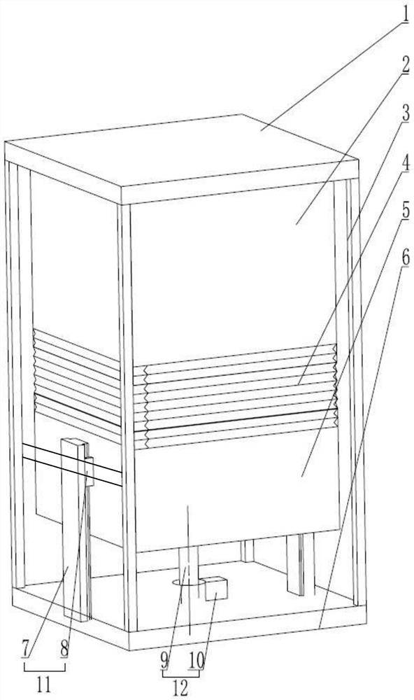
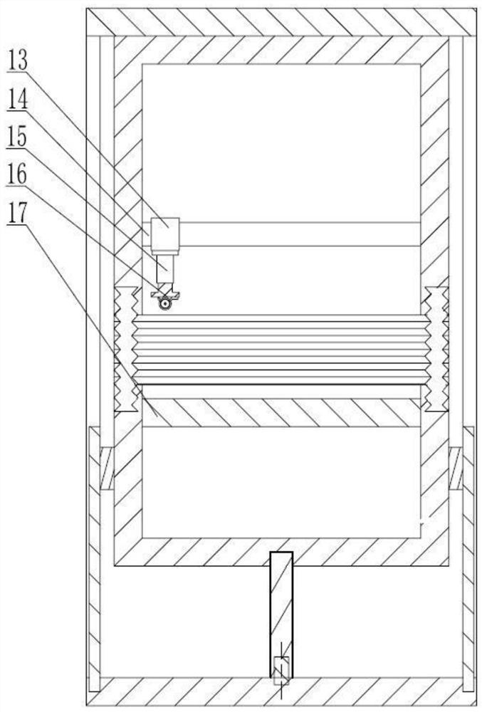
[0038] refer to Figure 1 to Figure 3 As shown, a laser sintering printer includes a frame 3, an upper cylinder body 2, a lower cylinder body 5, a workbench 17, a powder spreading powder supply mechanism 23, an orientation guide rail 11, a lead screw nut pair 12 and a telescopic structure 4; The upper and lower cylinder bodies are connected to the telescopic structure 4 through fitting, so that the entire molding cylinder is a closed space; the workbench 17 is fixedly connected to the inside of the lower cylinder body 5 by welding.

[0039] In order to realize 3D printing work, the screw nut pair 12 is located at the center of the bottom end of the lower cylinder body 5, which is consistent with the Z-axis direction of the forming cylinder body; Lead screw nut pair 12 makes lower cylinder body 5 do the orientation guide rail 11 of lifting motion.

[0040] In this embodiment, the directional guide rail 11 includes a slider 8 and a static guide rail 7, and the static guide rail...

Embodiment 2

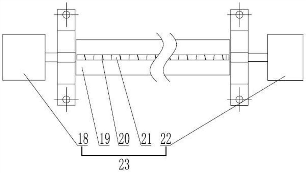
[0055] The difference between this embodiment and Example 1 is that the diameter of the powder outlet holes on the powder outlet sieve is 70um, the number of powder outlet holes on the powder outlet sieve is 2300, and the screw powder feeding mechanism and the powder outlet The gap between the insides of the powder supply and powder sets is 0.2mm; the purpose of this design is to adapt to the particle size of the powder. If the particle size of the powder is below 70um, the powder outlet sieve will filter the powder with a diameter greater than 70um, because in 3D printing Among them, the diameter of the powder that does not meet the requirements will reduce the printing quality; the powder output can be adjusted to adapt to the small area of ​​the workbench and improve the efficiency of powder supply.

[0056] The working mode and other structures and connection modes of this embodiment are the same as those in Embodiment 1.

Embodiment 3

[0058] The difference between this embodiment and embodiment 1 is that the diameter of the powder outlet holes on the powder outlet sieve is 120um, the number of powder outlet holes on the powder outlet sieve is 546, and the screw powder feeding mechanism and the powder outlet The gap between the insides of the powder supply and powder sets is 0.1mm; its purpose is consistent with that described in Example 3, that is, if the particle size of the powder is below 120um, the powder outlet sieve will filter powders with a diameter greater than 120um, because in 3D printing , The diameter of the powder that does not meet the requirements will reduce the printing quality; the powder output can be adjusted to adapt to a large-area workbench and improve the efficiency of powder supply.


PUM

PropertyMeasurementUnit
diameteraaaaaaaaaa
diameteraaaaaaaaaa

Abstract

The invention discloses a laser sintering printer, which belongs to the field of additive manufacturing and includes a frame, a cylinder body, a workbench, a lead screw and a nut pair, and a powder supply and spreading mechanism; the cylinder body includes an upper cylinder body and a lower cylinder body, The upper and lower cylinders are connected by a telescopic structure; the workbench is located inside the lower cylinder and is fixedly connected with the lower cylinder; the screw nut pair is located at the center of the outer bottom of the lower cylinder, and is aligned with the Z axis of the cylinder. Consistent; the outside of the lower cylinder is provided with a directional guide rail that supports the cylinder and cooperates with the screw nut pair to make the lower cylinder move up and down. The purpose of the present invention is to provide a retractable laser sintering printer which can solve the problems of sealing, cleaning, reducing the quality of the molding cylinder, and improving the quality and efficiency of powder spreading.

Description

technical field [0001] The invention relates to the field of additive manufacturing, in particular to a laser sintering printer. Background technique [0002] With the development of 3D printing technology, the research on laser sintering technology is getting more and more in-depth. The process of laser sintering processing parts is that the powder supply mechanism spreads a certain amount of powder on the workbench, and then the powder is leveled by the scraper, and then the laser head sinters the current layer of powder. After the processing is completed, the supplier The powder spreading mechanism spreads the powder, continues to scrape, and repeats this process to obtain the required parts. [0003] In laser sintering technology, the sealing condition of the molding chamber is very high. Most of the current technologies focus on how to use external conditions to realize the sealing state of the molding chamber, such as setting a vacuum pump outside the molding chamber ...

Claims


Application Information

Patent Timeline
Patent Type & Authority Patents(China)
IPC IPC(8): B29C64/153B29C64/205B29C64/218B29C64/20B29C64/25B29C64/194B33Y30/00B33Y40/00B33Y10/00
CPCB29C64/153B29C64/205B29C64/218B29C64/20B29C64/25B29C64/194B33Y30/00B33Y40/00B33Y10/00
Inventor 郑力铭康柱黄继霖吴春蕾康小青尹海龙
Owner 四川交大至信教育科技有限公司
Why Eureka
Try Eureka