Anti-collision guardrail with buffering function

An anti-collision guardrail and functional technology, applied in the direction of roads, road safety devices, roads, etc., can solve the problems of easily damaged guardrails, vehicle rollover, and inability to release impact energy.

Active Publication Date: 2019-12-10
吉林建筑科技学院
View PDF25 Cites 9 Cited by
  • Summary
  • Abstract
  • Description
  • Claims
  • Application Information

AI Technical Summary

Problems solved by technology

[0009] The invention provides an anti-collision guardrail with a buffer function, which can solve the problems in th...

Method used


Image

  • Anti-collision guardrail with buffering function
  • Anti-collision guardrail with buffering function
  • Anti-collision guardrail with buffering function

Examples


Embodiment 1

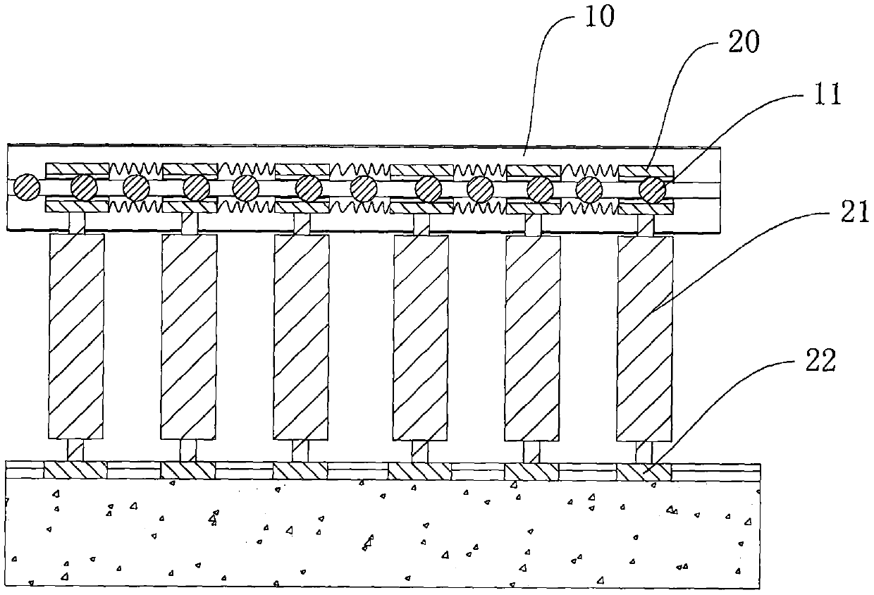
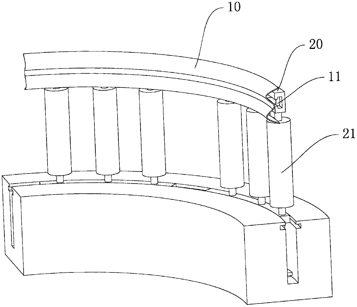
[0032] like figure 1 As shown, an embodiment of the present invention provides a bumper barrier with a buffer function, including a wave barrier 10, and further includes:

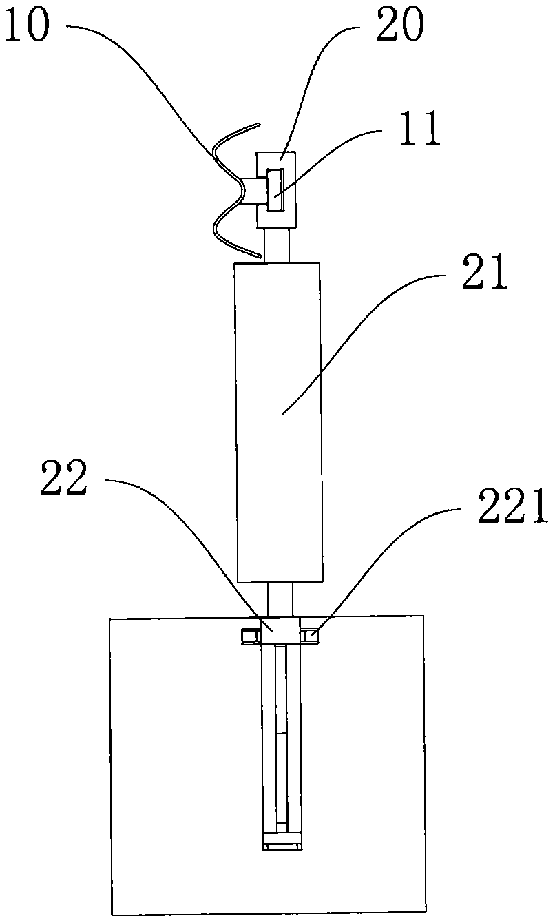
[0033] The primary buffer mechanism includes a plurality of rollers 21, a guide block 20 arranged at the upper end of the roller 21 and corresponding to the roller 21 one-to-one, an upper support plate 22 arranged at the lower end of the roller 21 and corresponding to the roller 21 one-to-one, and rotatably arranged on the Several guide wheels 11 on the wave guardrail 10, the roller 21 can rotate relative to the guide block 20 and the upper support plate 22, the upper support plate 22 is slidably arranged on the installation foundation, the guide block 20 is provided with a guide groove, and the guide groove is C-shaped Structure, the guide wheel 11 is connected to the wave guardrail 10 through a rotating shaft, the guide wheel 11 is located in the guide groove, the rotating shaft extends out of the guide g...

Embodiment 2

[0036] On the basis of Example 1, as Figure 2 to Figure 8 As shown, this embodiment also includes a secondary buffer mechanism, such as figure 2As shown, it includes a lower support plate 25, a telescopic mechanism and two buffer springs 26, the upper support plate 22 corresponds to the lower support plate 25 one-to-one, and the telescopic mechanism includes a first connecting rod 23 and a second connecting rod 24, the first connecting rod 23 and the second connecting rod 24. The rod 23 and the second connecting rod 24 are crossed. The first connecting rod 23 is provided with a first sliding groove 231, the second connecting rod 24 is provided with a second sliding groove 241, the first sliding groove 231 and the second sliding groove 241. They are connected by a pin shaft, the pin shaft is slidably arranged in the first chute 231 and the second chute 241, the lower support plate 25 is provided with a support block 251, and the support block 251 is provided with a vacant chu...

Embodiment 3

[0040] like Figure 9 and Figure 10 As shown, several baffles 211 are arranged on the drum 21. When the drum 21 rotates, the baffles 211 are driven to rotate. turn to.

[0041] Wherein, the cross section of the baffle 211 is in a triangular structure that gradually converges in the direction away from the drum 21 .

[0042] When the vehicle hits, it drives the drum 21 to rotate, and when the drum 21 rotates, it drives the baffle 211 to rotate. When the first drum 21 rotates, it drives the baffle 211 to rotate. Taking the clockwise direction as an example, the baffle 211 drives the adjacent other A roller 21 rotates in the opposite direction, that is, counterclockwise. When the baffle plate 211 hits the adjacent baffle plate 211, it will generate an impact and consume a part of the energy, and when the vehicle continues to move, it will hit the next adjacent roller. The baffle 211 on the 21, and at this time, the rotation of the baffle 211 is opposite to the moving directio...


PUM


Abstract

The invention discloses an anti-collision guardrail with a buffering function, and belongs to the field of guardrails. The device comprises a corrugated guardrail and further comprises a one-time buffering mechanism. The one-time buffering mechanism comprises a plurality of rollers, guide blocks arranged at the upper ends of the rollers and in one-to-one correspondence with the rollers, upper support plates arranged at the lower ends of the rollers and in one-to-one correspondence with the rollers and a plurality of guide wheels rotationally arranged on the corrugated guardrail. The rollers can rotate relative to the guide blocks and the upper support plates. The upper support plates are slidably arranged on a mounting foundation. Guide grooves are formed in the guide blocks. Guide wheelsare located in the guide grooves. Every two adjacent guide blocks are connected through a reset spring. According to the anti-collision guardrail with the buffering function, the one-time buffering mechanism enables a vehicle to generate a certain guiding effect under the driving of the rotation of the rollers during impact, so that the possibility of rollover is reduced, deformation and damage caused by impact force on the rollers can be reduced, meanwhile, the impact force of the vehicle can be absorbed by the energy consumption, and the damage degree of the vehicle is reduced.

Description

technical field [0001] The invention relates to the field of guardrails, in particular to an anti-collision guardrail with a buffering function. Background technique [0002] When the vehicle is traveling on the road, traffic accidents caused by various reasons will cause the vehicle to deviate from the road. In order to prevent the vehicle from rushing out of the roadbed, wave guardrails or steel rope protection are widely used on roads (especially highways) at this stage. Bar, which has the function of blocking and constraining the vehicle. [0003] In practice, the disadvantages of corrugated guardrails or wire rope guardrails are: [0004] The guardrail is made of metal and is in rigid contact with the vehicle body, and the collision will cause great damage to the vehicle and personnel. [0005] 1. Due to its own structure, the guardrail has poor strength and is easily damaged in a collision. [0006] 2. When a collision occurs, the vehicle often stops suddenly, and t...

Claims


Application Information

Patent Timeline
IPC IPC(8): E01F15/02
CPCE01F15/02
Inventor 赵海霞解雅军郎原龙
Owner 吉林建筑科技学院
Why Eureka
Try Eureka