Wind turbine generator active regulation method and method based on wind speed advance measurement
A technology of wind turbines and adjustment methods, which is applied in wind power generation, wind turbines, control of wind turbines, etc., and can solve the problems of increased fatigue load, shortened life of the pitch system, and insufficient performance of wind turbines, etc.
Active Publication Date: 2019-12-10
CENT SOUTH UNIV
4 Cites 9 Cited by
AI-Extracted Technical Summary
Problems solved by technology
[0004] The present invention aims to solve the problem of insufficient performance of wind turbines caused by existing control technologies
The present invention provides a wind turbine active power adjustment method based on wi...
Method used
[0088] Considering that the wind speed is constantly changing, the impeller rotation of large-scale wind turbines and the pitch system belong to the large inertial system, and the long period T is discretized into n sections of short periods Δt in order to achieve a better control effect. The short period Δt is preferably 1s.
[0169] The present invention is based on the active power control method of the variable-speed constant-frequency wind turbine that reduces the pitch action of the wind speed measurement in advance, and obtains the optimal given pitch angle sequence and the optimal given torque sequence by calculating the cost functio...
Abstract
The invention discloses a wind turbine generator active regulation method based on wind speed advance measurement. The method comprises the following steps of 1, establishing a cost function accordingto an active regulation optimization objective of a wind generating set; 2, establishing a wind generating set state prediction equation by using a wind speed and wind generating set model in advance; 3, solving the cost function by utilizing a prediction state value to obtain a sequence of the optimal given pitch angle and a sequence of a given torque; and 4, taking the sequence of the optimal given pitch angle of the wind generating set and the first element of the sequence of the given torque as an output of a controller. Under the high-speed wind condition, when the active power output ismet to be equal to the target power, the action of a variable-pitch mechanism can be reduced, the fatigue load of the variable-pitch system is reduced, and the maximum power tracking operation is realized under a low-speed wind condition. In each prediction step size, only one of a pitch angle sequence or a torque sequence is adopted as a candidate limited control set, so that the operation amount of the controller is greatly reduced, and the engineering applicability is enhanced.
Application Domain
Data processing applicationsWind motor control +6
Technology Topic
Wind forceElectricity +10
Image
Examples
- Experimental program(1)
Example Embodiment
[0081] In order to make the object, technical solution and advantages of the present invention clearer, the present invention will be further described in detail below in conjunction with the accompanying drawings. Obviously, the described embodiments are only some embodiments of the present invention, rather than all embodiments . Based on the embodiments of the present invention, all other embodiments obtained by persons of ordinary skill in the art without making creative efforts belong to the protection scope of the present invention.
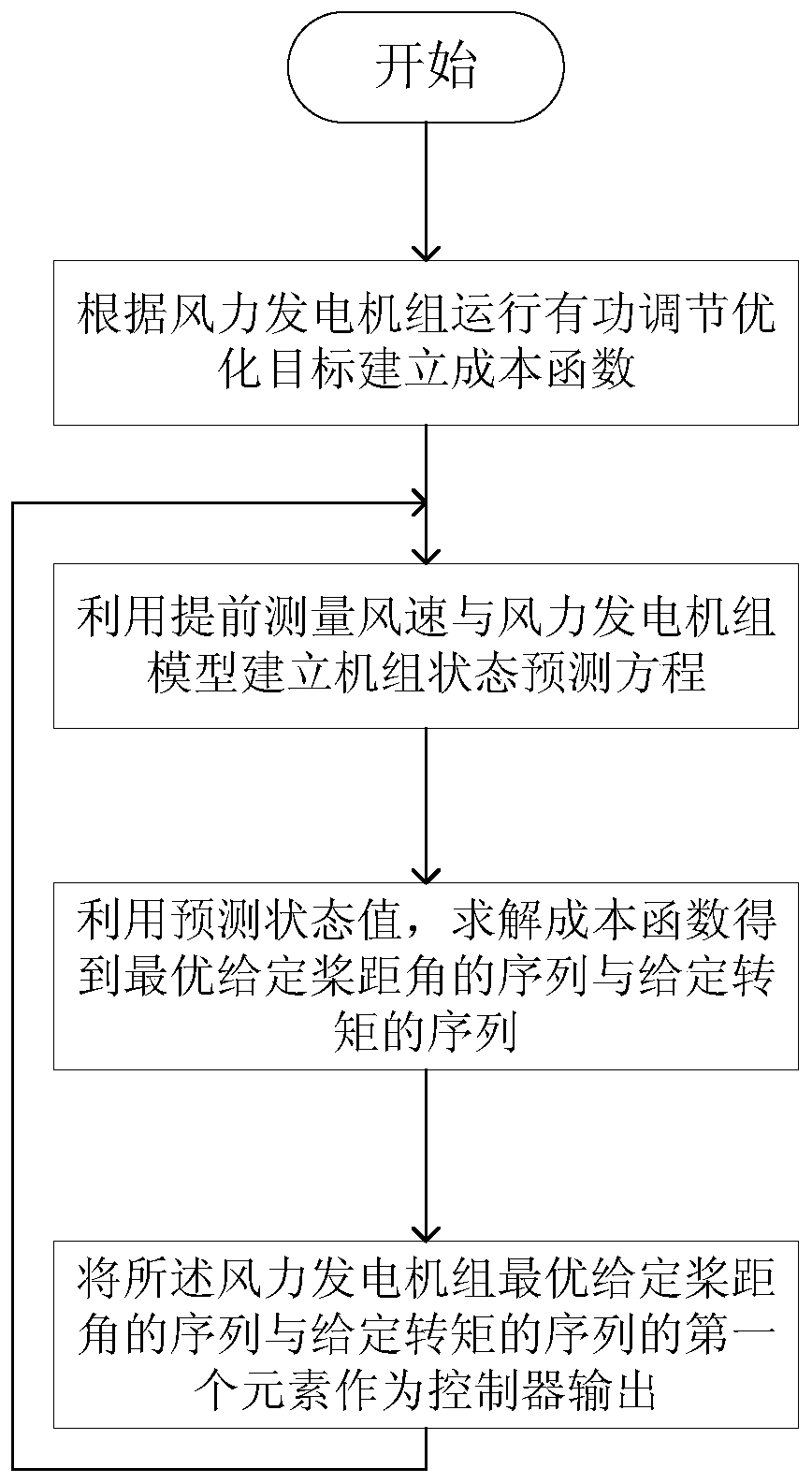
[0082] combine figure 1 , the active power control method of the variable-speed constant-frequency wind turbine set based on the wind speed measurement in advance to reduce the pitch action of the present invention includes the following steps:
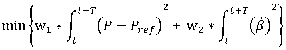
[0083] In step 1, a cost function is established according to the optimization target of active power regulation of wind turbine operation.
[0084] Step 1-1, determine the target power P of the wind turbine ref; Determine the long-term prediction period T and the prediction step size n. Considering the change of wind speed and the accuracy of wind measuring devices, the long period T and the forecast step size n should not be too large.
[0085] Step 1-2, since the goal of the active power control operation of the variable speed wind turbine is to keep the output active power at the target power P ref , and taking into account the need to avoid too frequent pitch angle actions, so within a specific time T, the optimization objective of the limited active power control operation of the variable-speed wind turbine can be expressed by the following cost function:
[0086]
[0087] Among them, w 1 and w 2 is a weighting factor, which can be determined by a trial-and-error procedure. The setting principle of its value is: to ensure that the power fluctuation is within the allowable range, and to minimize the pitch angle action. P is the wind turbine power, is the pitch angle change rate.
[0088] Considering that the wind speed is constantly changing, the impeller rotation and pitch system of large-scale wind turbines belong to the large inertia system, and the long period T is discretized into n short periods Δt in order to achieve better control effect. The short period Δt is preferably 1s.
[0089] Then the optimization objective of the variable speed wind turbine within a specific time T is:
[0090]
[0091] Among them, P k+i is the wind turbine power in the i-th prediction period of the k-th control period, β k+i with beta k+i-1 It is given for the wind turbine pitch angle of the i-th and i-1 prediction periods.
[0092] Steps 1-3, according to the actual operating state of the wind turbine, it is necessary to constrain the finite control set of the candidate given pitch angle of the wind turbine, the finite control set of the candidate given torque and the corresponding speed value. Obviously, the value of the pitch angle β is not less than 0 and not greater than its allowable maximum value. Considering the safety of the unit and the demand for grid connection, the speed should also be changed within a certain range. Since the wind turbine pursues the maximum power tracking and the given torque increases with the increase of the speed at low wind speed, and the given torque of the output target power decreases with the increase of the speed at high wind speed, so the torque at the speed of ω r_low obtain the maximum value. where ω r_low is the optimal power point P opt with P ref The rotation speed corresponding to the intersection point of , corresponds to a series of different values when the pitch angle β is different, and the ω used in all the following descriptions r_low The values are all the values corresponding to the pitch angle β at the current moment. In summary, the cost function constraints are as follows:
[0093] 0≤β≤β max (3)
[0094]
[0095] ω r_cut ≤ω r ≤ω r_high (5)
[0096] beta max is the maximum pitch angle; T grare is the rated torque; ω r_cut is the cut-in speed of wind speed; ω r_high is the maximum speed limit.
[0097] Steps 1-4, get ω r_low Corresponding relationship with the pitch angle β.
[0098] Different types of wind turbines ω r_low Different from the corresponding relationship of the pitch angle β, select different pitch angles, draw the optimal power curves corresponding to different pitch angles, and find the optimal power curve and the target power P ref The speed ω corresponding to the intersection point r_low , record ω r_low It corresponds to the pitch angle β and is drawn into a table.
[0099] The optimal power curve can be obtained as follows:
[0100] The formula for calculating the optimal power of wind turbines is:
[0101]
[0102] Where ρ is the air density, R is the radius of the rotor, V is the wind speed, C p (λ, β) is the wind energy capture coefficient, K opt Can be expressed as:
[0103] K opt =0.5ρπR 5 C p (λ,β)/λ 3 (7)
[0104] When β is a certain constant, K opt λ is the maximum value obtained when the optimum tip speed ratio is obtained. Use formula (7) to find the most value K opt , and then according to formula (6), the optimal power curves at different pitch angles can be drawn.
[0105] Step 2, using the wind speed measured in advance and the model of the wind turbine to establish the state prediction equation of the wind turbine.
[0106] Step 2-1, get the current wind turbine pitch angle given β k , torque given T gk and the speed ω rk , based on which a candidate finite control set is given.
[0107] In order to avoid the problem that the finite control set that adopts the two outputs of pitch angle and torque at the same time will cause a large amount of calculation of the cost function, in each prediction cycle, the ω r_low and speed ω rk+i-1 The comparison of , given only one of the control output sets, the other output set will be derived on this basis.
[0108] That is, at the speed ω rk+i-1 less than ω r_low , at this time only the finite control set T of the given torque gk+i , a finite control set β for a given pitch angle k+i Given that all elements are β k+i-1 -Δβ (Δβ is the maximum pitch angle of the wind turbine within Δt, when Δt is selected as 1s, Δβ can be selected as 8°); speed ω rk+i-1 Greater than or equal to ω r_low , at this time only the finite control set β of the given pitch angle k+i , the finite control set T for a given torque gk+i A given element is given by the formula P ref /ω rk+i N is drawn.
[0109] Among them, about the rotational speed ω rk+i-1 The description of is as follows: when i=1, the speed ω rk+i-1 Indicates the measured speed at the current moment; when i>1, the speed ω rk+i-1 Indicates the predicted rotation speed of the i-1th prediction cycle, and the predicted rotation speed can be deduced cyclically according to the formula in step 2-3. In the following description, the rotational speed ω rk+i-1 The meanings are the same as here, and will not be repeated here.
[0110] In the kth control period, the ith (i∈(1,2...n))th prediction period is given a pitch angle finite control set β k+i With the given torque limited control set T gk+i The setting method of is as follows:
[0111] (1) When the speed ω rk+i-1 Greater than or equal to ω r_low Time:
[0112] Given the pitch angle β in the first prediction period (i.e. when i=1) k+1 The collection is set to:
[0113]
[0114] where m 1 is the number of elements in the finite control set, which can be appropriately selected between 10 and 20 according to the operation speed of the controller; and are the maximum and minimum values of a given pitch angle, respectively, and their values can be expressed as:
[0115]
[0116]
[0117] where Δβ 1 is the size of the change range of the given pitch angle, which can be taken as 5°.
[0118] At this time, the given torque T gk+1 for:
[0119] T gk+1 =P ref /ω rk+1 N (11)
[0120] The remaining n-1 prediction periods (i.e. when i>1) give the pitch angle β k+i The set of (i>1) is set to:
[0121]
[0122] where m 2 is the number of elements in the finite control set, in order to reduce the amount of calculation, it should be properly compared to m 1 Small, can take a value between 6 and 10; and For the maximum and minimum values of the given pitch angle at this time, its value is set as:
[0123]
[0124]
[0125] where Δβ 2 For a given pitch angle variation range, Δβ can be taken 2 =Δβ 1.
[0126] The corresponding given torque T gk+i (i>1) is:
[0127] T gk+i =P ref /ω rk+i N (15)
[0128] (2) Conversely, when the speed ω rk+i-1 less than ω r_low Time:
[0129] The first forecast period (i.e. when i=1) T gk+1 The given can be expressed as:
[0130]
[0131] where m 3 is the number of elements in the finite control set, which can be appropriately selected between 10 and 20 according to the operation speed of the controller; and are the maximum value and minimum value of the given torque respectively, and their values are set as:
[0132]
[0133]
[0134] where ΔT g1 In order to specify the size of the torque variation range, it needs to be selected according to the model of the wind turbine.
[0135] At this time, given the pitch angle β k+1 for:
[0136] beta k+1 = β k -Δβ (19)
[0137] The remaining n-1 cycles (i.e. when i>1) give torque T gk+i The set of (i>1) is set to:
[0138]
[0139] where m 4 is the number of finite control set elements; and For the maximum and minimum values of the given torque at this time, its value is set as:
[0140]
[0141]
[0142] where ΔT g2 For the size of the given torque variation range, ΔT can be taken g2 =ΔT g1.
[0143] The corresponding given pitch angle β k+i (i>1) is:
[0144] beta k+i = β k+i-1 -Δβ (23)
[0145] Step 2-2, establish the wind turbine model.
[0146] Get the future average wind speed V measured in advance k+1 V k+2 V k+3 …V k+n. The wind turbine is modeled to get:
[0147] P r =T r ω r =0.5ρπR 2 V 3 C p (λ,β) (24)
[0148]
[0149] Among them, P r is the captured power of the wind turbine from the air, T r is the aerodynamic moment, ω r is the rotor speed, ρ is the air density, R is the rotor radius, V is the wind speed, C p (λ, β) is the wind energy capture coefficient, which can be calculated according to the fitting function, J R is the combined inertia of the impeller-generator two-mass model, T g is the generator torque, and N is the gearbox ratio.
[0150] Step 2-3, predicting the impeller speed.
[0151] Using the formula (24)(25) in step 2-2, the predicted impeller speed ω can be derived rk+1 Expressed as:
[0152]
[0153] Considering the calculation amount and memory capacity of the controller, some parameters of the above formula are approximated, where:
[0154] lambda k+1 ≈ω rk R/V k+1 (27)
[0155] C p The calculation of (λ, β) can be calculated according to the fitting function, as follows:
[0156]
[0157]
[0158] Among them, a 1 、a 2 、a 3 、a 4 、a 5 、a 6 , b 1 , b 2 The parameters are constant and depend on the aerodynamic properties of the wind turbine blades.
[0159] Substituting the given pitch angle sequence and the given torque sequence in step 2-1 to solve the equation, the predicted impeller speed ω can be obtained rk+1 sequence.
[0160] Step 3, using the predicted state value, the cost function is solved to obtain the optimal given pitch angle sequence and given torque sequence.
[0161] In the cost function, the predicted power expression of the wind turbine is:
[0162] P k+i =T gk+i ω rk+i N (30)
[0163] In summary, combined with figure 2, the process of solving the cost function is: if in the first prediction period, the current measured speed ω rk ≥ω r_low , at this time, the candidate given pitch angle finite control set set by formula (8), the candidate given torque finite control set set by formula (11) and formula (27) are substituted into formula (26), and the predicted Speed sequence ω rk+1. Conversely, if in the first prediction period, the current measured speed ω rk r_low , at this time, the candidate given torque finite control set set by formula (16), the candidate given pitch angle finite control set set by formula (19) and formula (27) are substituted into formula (26), and the predicted Speed sequence ω rk+1.
[0164] In the next forecast period, according to the predicted speed sequence ω obtained in the previous forecast period rk+i-1 (i>1, the same below) as the basis for a given control output set.
[0165] If the predicted speed ω rk+i-1 ≥ω r_low , at this time, the candidate given pitch angle finite control set set by formula (12), the candidate given torque finite control set set by formula (15) and formula (27) are substituted into formula (26), and the predicted Speed sequence ω rk+i. Conversely, if the predicted speed ω rk+i-1 r_low , at this time, the candidate given torque finite control set set by formula (20), the candidate given pitch angle finite control set set by formula (23) and formula (27) are substituted into formula (26), and the predicted Speed sequence ω rk+i. According to the above method, from i=2 to i=n in turn, the given pitch angle sequence β in n prediction periods can be obtained k+i with a given torque sequence T gk+i and the predicted speed sequence ω rk+i , i=(1,2...n).
[0166] At the same time, in each forecast period, the constraints in steps 1-3 should be considered. Use formula (3) and formula (4) to limit the elements in the candidate given pitch angle finite control set and the candidate given torque finite control set. At the same time, elements in the given pitch angle sequence and the given torque sequence corresponding to the predicted rotational speed that do not meet the requirements of formula (5) are eliminated.
[0167] Finally, the formula (30) is substituted into the cost function formula (2), and the optimal given pitch angle sequence and the given torque sequence that make the cost function obtain the minimum value are selected.
[0168] Step 4, outputting the first element of the optimal given pitch angle sequence and given torque sequence of the wind power generating set as the controller.
[0169] The active power control method of the variable-speed constant-frequency wind turbine with reduced pitch action based on wind speed measurement in advance in the present invention obtains the optimal given pitch angle sequence and the optimal given torque sequence by calculating the cost function, and respectively The first element of the group sequence is used as the pitch angle output and torque output of the controller, so that the wind turbine can realize the maximum power tracking operation at low wind speed, and the active power output is equal to the target power at high wind speed, and as much as possible Reduce pitch motion. This method plays an important role in reducing the active power output fluctuation of the unit, reducing the action of the pitch mechanism, and reducing the fatigue load of the pitch system. At the same time, it also ensures the safety and stability of the unit through constraints.
[0170] It should also be noted that the term "comprises", "comprises" or any other variation thereof is intended to cover a non-exclusive inclusion such that a process, method, article, or apparatus comprising a set of elements includes not only those elements, but also includes Other elements not expressly listed, or elements inherent in the process, method, commodity, or apparatus are also included. Without further limitations, an element defined by the phrase "comprising a ..." does not exclude the presence of additional identical elements in the process, method, article or apparatus comprising said element.
[0171] Those skilled in the art should understand that the embodiments of the present application may be provided as methods, systems or computer program products. Accordingly, the present application can take the form of an entirely hardware embodiment, an entirely software embodiment or an embodiment combining software and hardware aspects. Furthermore, the present application may take the form of a computer program product embodied on one or more computer-usable storage media (including but not limited to disk storage, CD-ROM, optical storage, etc.) having computer-usable program code embodied therein.
[0172] While the invention has been described above with reference to various embodiments, it should be understood that many changes and modifications may be made without departing from the scope of the invention. It is therefore intended that the foregoing detailed description be regarded as illustrative rather than restrictive, and that it be understood that the following claims, including all equivalents, are intended to define the spirit and scope of the invention. The above embodiments should be understood as only for illustrating the present invention but not for limiting the protection scope of the present invention. After reading the content of the present invention, the skilled person can make various changes or modifications to the present invention, and these equivalent changes and modifications also fall within the scope defined by the claims of the present invention.
PUM


Description & Claims & Application Information
We can also present the details of the Description, Claims and Application information to help users get a comprehensive understanding of the technical details of the patent, such as background art, summary of invention, brief description of drawings, description of embodiments, and other original content. On the other hand, users can also determine the specific scope of protection of the technology through the list of claims; as well as understand the changes in the life cycle of the technology with the presentation of the patent timeline. Login to view more.