
A multi-functional experimental platform for the transient response characteristics of the cavity
A transient response and multi-functional technology, applied in the direction of jet engine testing, gas turbine engine testing, etc., can solve problems such as the inability to conduct multi-cavity transient characteristic coupling experiments, and achieve the effect of easy replacement, assembly, and disassembly
- Summary
- Abstract
- Description
- Claims
- Application Information
AI Technical Summary
Problems solved by technology
Method used
Image

Examples
Embodiment 1
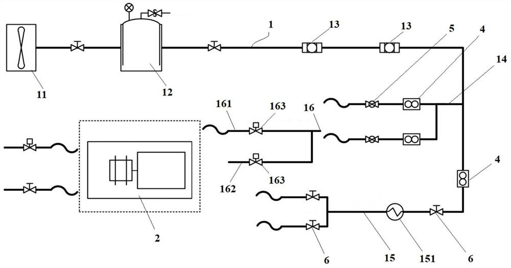
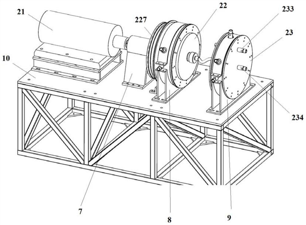
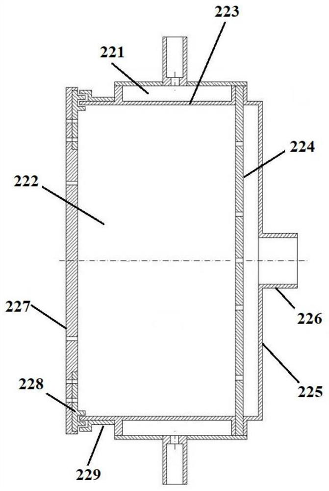
[0042] Such as Figure 1 to Figure 4As shown, this embodiment provides a multi-functional test bench for the transient response characteristics of the cavity, including a gas supply system 1, an experimental section 2 that can communicate with the gas supply system 1, and a gas supply system installed on the gas supply system 1 and the experimental section 2 Test system; air supply system 1 comprises air compressor 11, air storage tank 12 and air filter 13 that are sealed and communicated through pipelines successively, and the pipeline through air filter 13 is divided into cold air pipeline 14 and hot air pipeline 15, cold air pipeline 14 and The hot air pipeline 15 is equally divided into two branches, and the two branches near the cold air pipeline 14 are provided with a solenoid valve pipeline 16 that can communicate with it. The solenoid valve pipeline 16 is divided into a first solenoid valve branch 161 and a second solenoid valve branch. The branch 162 is provided with ...
PUM
 Abstract
Description
Claims
Application Information