Honeycomb wheel core structure in zeolite wheel

A technology of zeolite runner and honeycomb wheel, which is used in gas treatment, dispersed particle separation, membrane technology and other directions, can solve the problems of low adsorption efficiency, cannot be too fast, and desorption is not complete enough, so as to improve the concentration ratio and improve the economy. Benefit, good adsorption effect

Inactive Publication Date: 2019-12-13
SHANGHAI LANBAO ENVIRONMENTAL PROTECTION TECH CO LTD
View PDF10 Cites 0 Cited by
  • Summary
  • Abstract
  • Description
  • Claims
  • Application Information

AI Technical Summary

Problems solved by technology

[0004] 1) The problem of adsorption efficiency. Under the pressure of increasing environmental protection, the specific way to improve the adsorption efficiency of the current zeolite runner is to increase the diameter of the zeolite runner or increase the thickness of the zeolite runner. Each method will increase a lot of cost.
[0005] 2) The problem of physical characteristics, there is another problem with the zeolite runner, that is, the wind speed must be guaranteed against the wind, neither too fast nor too slow, which makes it impossible to increase the diameter of the runner at will to achieve higher processing efficiency
However, in the actual use process, it is found that once the concentration ratio exceeds 20 times, the adsorption efficiency will decrease. The reason is very simple. If the concentration ratio is increased and the adsorption air volume remains unchanged, the desorption air volume will be reduced, but this is still the case. Due to physical characteristics, the desorption air volume cannot be reduced indefinitely. When it is reduced to a certain extent, the wind speed is very slow, and the wind presents a laminar flow phenomenon in the honeycomb body, and the desorption is not complete. In the next adsorption working condition, the adsorption efficiency will inevitably decrease.

Method used


Image

  • Honeycomb wheel core structure in zeolite wheel
  • Honeycomb wheel core structure in zeolite wheel
  • Honeycomb wheel core structure in zeolite wheel

Examples


Embodiment

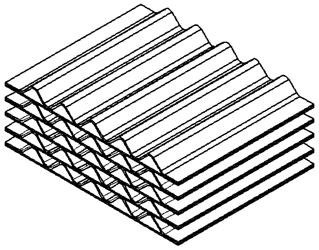
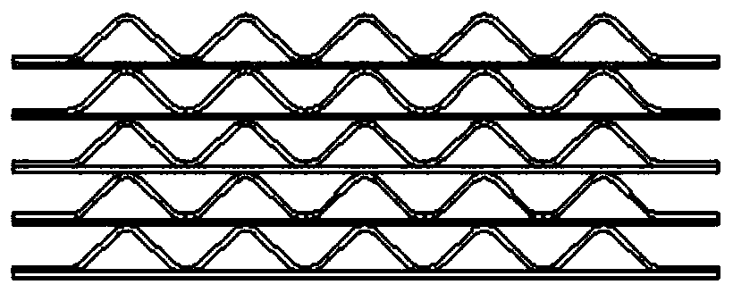
[0025] A honeycomb core structure in a zeolite runner according to the present invention includes a honeycomb core and a number of channels opened in the honeycomb core, and the channels are curved channels. The main body of the channel presents a wavy structure curved up and down. The wave-shaped structure of the channel has a plurality of waves. The distance between the crest and trough of the waveform in the vertical direction is 1-3 times the height of the channel.

[0026] All the channels are evenly distributed in the honeycomb wheel core.

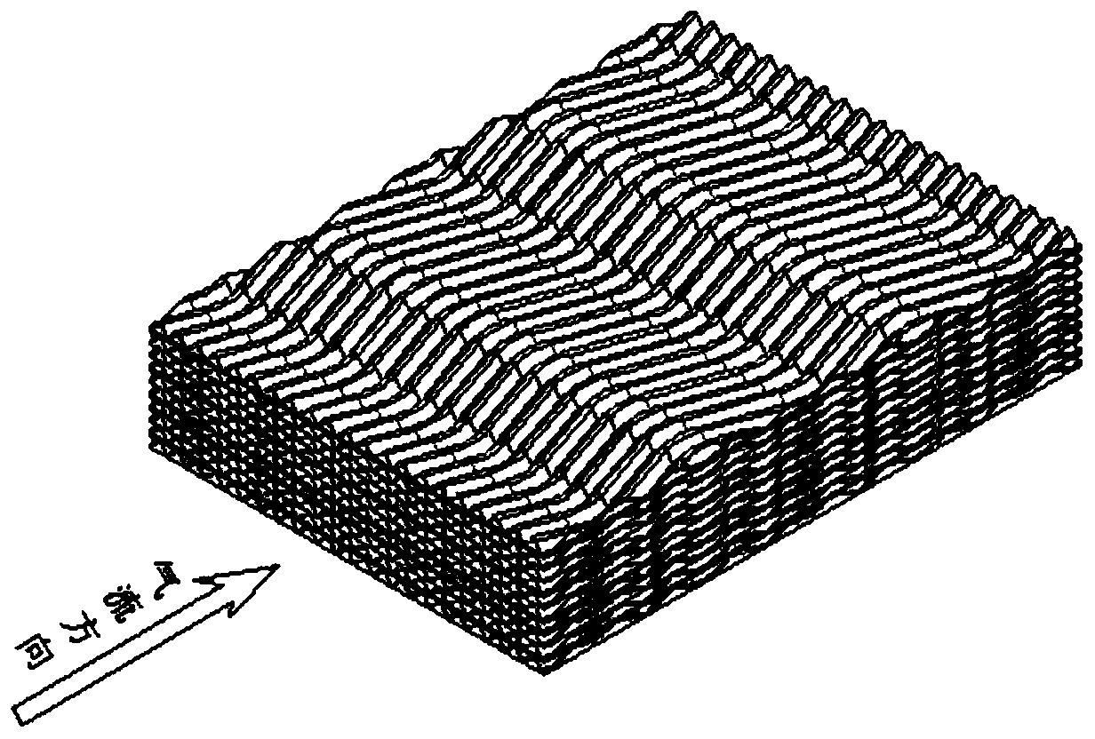
[0027] image 3 Based on the schematic diagram of the curved channel of the honeycomb wheel core, this figure is not the form of the final product, it is only for illustration.

[0028] In the production of actual products, the relationship between the pressure drop and efficiency of the airflow handled by the wheel core and the concentration ratio will be taken into account. The design of the curved channel has too many waves, th...


PUM


Abstract

The invention discloses a honeycomb wheel core structure in a zeolite rotating wheel, the honeycomb wheel core structure comprises a honeycomb wheel core and a plurality of pore passages formed in thehoneycomb wheel core, and the pore passages are bent pore passages. A main body of the pore passage is of a wavy structure which is bent up and down. And the wavy structure of the pore passage is provided with a plurality of waveforms. And the distance between the wave crest and the wave trough of the waveform in the vertical direction is 1-3 times of the height of the pore passage. And all the pore passages are uniformly distributed in the honeycomb wheel core. Compared with a traditional rotating wheel with the same size, the pressure loss is increased by about 5%-15%, the adsorption efficiency is improved by more than 30%, the concentration ratio is improved by more than 50% under the same adsorption efficiency, the concentration ratio can reach more than 40 times theoretically, and very obvious economic benefits and market prospects are achieved.

Description

technical field [0001] The invention relates to the field of zeolite runners, in particular to a honeycomb wheel core structure in the zeolite runner. Background technique [0002] The zeolite runner is used to concentrate the exhaust gas with high air volume and low concentration to the exhaust gas with high concentration and small air volume, so as to reduce the investment and operation costs of equipment and improve the high efficiency treatment of exhaust gas. [0003] The core of the zeolite runner is the honeycomb wheel core, and the adsorption material is loaded on the honeycomb wheel core, so that the adsorption process can be carried out. Existing honeycomb wheel core all adopts such as figure 1 and figure 2 Straight-hole single-facer corrugated construction shown. This method is more beneficial to the production of corrugated and attached to the adsorbent, but it has the following defects in the actual use process: [0004] 1) The problem of adsorption efficie...

Claims


Application Information

Patent Timeline
Patent Type & Authority Applications(China)
IPC IPC(8): B01D53/06
CPCB01D53/06B01D2257/708
Inventor 许永童许用疆谢勇倪江捷
Owner SHANGHAI LANBAO ENVIRONMENTAL PROTECTION TECH CO LTD
Why Eureka
Try Eureka