Transformer substation knife switch laser cleaning system

A laser cleaning and substation technology, applied in the field of laser cleaning systems, can solve the problems of cleaning dead angles, high labor intensity, and low efficiency, and achieve the effects of avoiding cleaning dead angles, reducing labor intensity, and improving cleaning efficiency

Inactive Publication Date: 2019-12-13
SUZHOU AISILAN PHOTOELECTRIC CO LTD
View PDF6 Cites 5 Cited by
  • Summary
  • Abstract
  • Description
  • Claims
  • Application Information

AI Technical Summary

Problems solved by technology

This treatment method has the following disadvantages: first, manual maintenance involves high-elevation operations, which is very inconvenient, and there are also potential safety hazards; second, there are dead spots for cleaning, and the degree of cleaning is difficult to control; third, the labor intensity is too large and the efficiency is low

Method used


Image

  • Transformer substation knife switch laser cleaning system
  • Transformer substation knife switch laser cleaning system
  • Transformer substation knife switch laser cleaning system

Examples


Embodiment 1

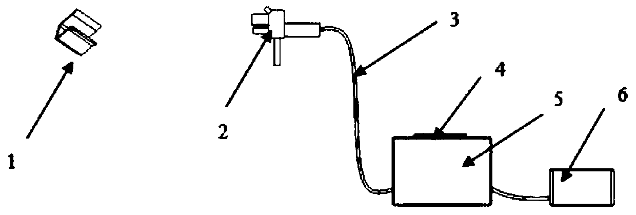
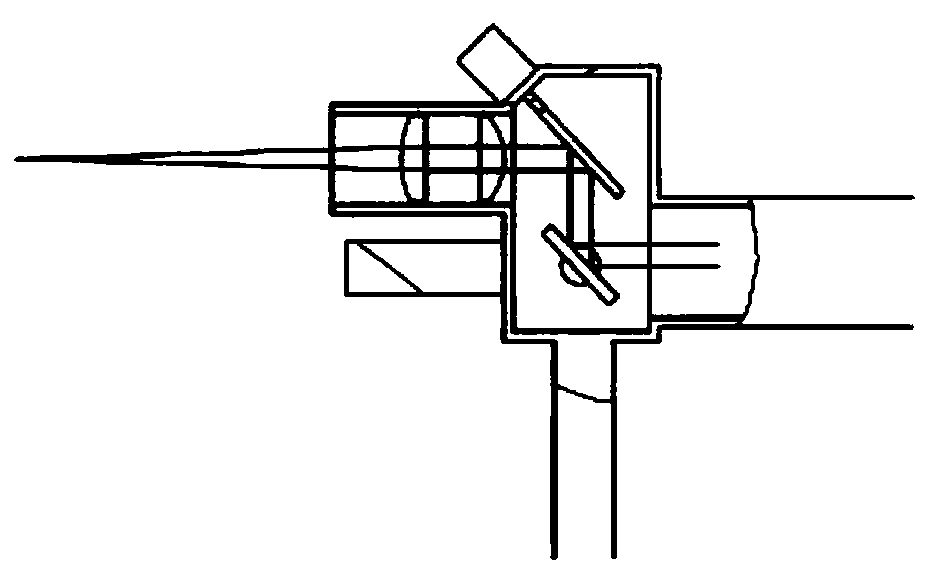
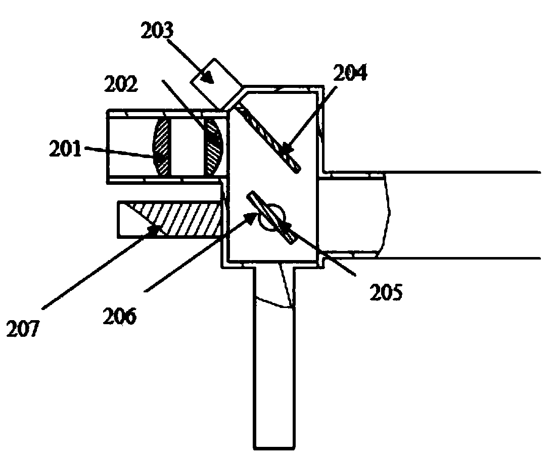
[0016] A laser cleaning system for substation knife switches, such as figure 1 As shown, it includes a laser generator 5 and a laser cleaning head 2 connected to the laser generator. The inside of the laser cleaning head is a cavity, one end is provided with an entrance, and the other end is provided with an exit port. There are first vibrating mirror 205 and second vibrating mirror 204 used to reflect the laser light from the incident angle to the exiting angle; the exit port is provided with a first lens 202 and a second lens 201 vertically parallel to each other. The second lens is used to focus the laser light reflected by the first and second vibrating mirrors. The laser generator 5 is powered by a power module 6, and the power module is preferably a lithium battery.

[0017] In the specific work, the laser light from the laser generator is transmitted to the entrance, and is emitted from the exit through the first and second lens reflection ports set inside the laser cl...

Embodiment 2

[0021] In addition to relying on the hand-held laser cleaning head to clean the contact surface of the knife gate, the laser cleaning head can also be fixed, and the angle of the laser beam can be adjusted by changing the angle of the first and second vibrating mirrors, so as to achieve the same effect as manual small swing laser. Cleaning the head does the same.

[0022] In this embodiment, the first and second vibrating mirrors are rotatably fixed in the cavity; the first and second vibrating mirrors are respectively connected with a first motor 206 and a second motor 203, and the first , The second motor is controlled by the controller 4 .

[0023] Under the action of the first motor, the first oscillating mirror achieves the effect of moving the outgoing laser up and down by changing the angle between it and the incident laser light; The included angle with the laser reflected by the first vibrating mirror achieves the effect of moving the outgoing laser left and right. ...


PUM


Abstract

The invention discloses a transformer substation knife switch laser cleaning system. The transformer substation knife switch laser cleaning system comprises a laser generator and a laser cleaning headconnected with the laser generator, wherein a cavity is formed in the laser cleaning head; an incident port is formed in one end of the cavity; an emergent port is formed in the other end of the cavity; a first galvanometer and a second galvanometer for reflecting laser from the incident angle to the emergent angle are arranged in the cavity; a first lens and a second lens are vertically and oppositely arranged at the emergent port in parallel; and the first lens and the second lens are used for focusing the laser reflected by the first galvanometer and the second galvanometer. According to the transformer substation knife switch laser cleaning system, an electrified transformer substation knife switch can be cleaned, hand-held remote operation can be achieved, and the laser cleaning parts can be adjusted through a controller, so that the blind angle of cleaning is avoided, the work intensity is reduced, and the cleaning efficiency of the transformer knife switch is improved.

Description

technical field [0001] The invention relates to the technical field of laser cleaning, in particular to a laser cleaning system used for the opening and closing of a switch of a substation. Background technique [0002] During the operation of the substation knife switch, due to the overcurrent thermal effect of the substation knife switch, when the contact resistance of the contact is too large, it is prone to overheating, the static contact of the knife switch isolating switch is jammed, and the opening and closing are not in place. It also happens from time to time; the reason is that the moving and static contacts of the switch knife and the internal transmission accessories are seriously accumulated. The current method to deal with such problems is to cut off the power of the equipment and manually clean the contact surface to reduce the amount of dust on the surface, thereby reducing the contact resistance. This processing method has the following disadvantages: first...

Claims


Application Information

Patent Timeline
Patent Type & Authority Applications(China)
IPC IPC(8): B08B7/00
CPCB08B7/0042
Inventor 何舟周健周倩
Owner SUZHOU AISILAN PHOTOELECTRIC CO LTD
Why Eureka
Try Eureka