
Continuous cyclic powder spreading structure and additive manufacturing molding equipment

A technology of additive manufacturing and powder spreading, which is applied in the field of continuous circulating powder spreading structure and additive manufacturing forming equipment, can solve the problems of powder spreading and scanning, so as to improve the powder utilization rate, ensure the printing effect, and improve the forming efficiency Effect

Pending Publication Date: 2019-12-13
NAT INST CORP OF ADDITIVE MFG XIAN
View PDF0 Cites 11 Cited by
  • Summary
  • Abstract
  • Description
  • Claims
  • Application Information

AI Technical Summary

Problems solved by technology

[0004] The purpose of the present invention is to provide a continuous cycle powder spreading structure and additive manufacturing forming equipment to overcome the defects that powder spreading and scanning cannot be performed in existing equipment, and to realize simultaneous powder spreading and scanning in the SLM forming process, that is, powder spreading at the same time Efficient printing process with edge scan

Method used


Image

  • Continuous cyclic powder spreading structure and additive manufacturing molding equipment
  • Continuous cyclic powder spreading structure and additive manufacturing molding equipment
  • Continuous cyclic powder spreading structure and additive manufacturing molding equipment

Examples


Embodiment Construction

[0030] The present invention is described in further detail below in conjunction with accompanying drawing:

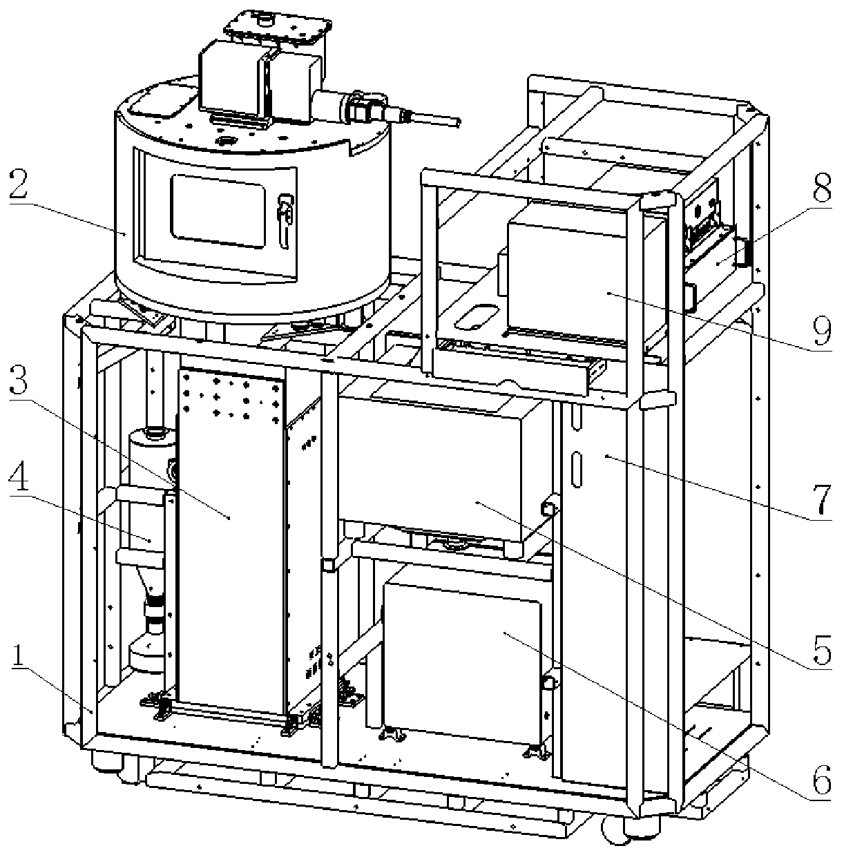
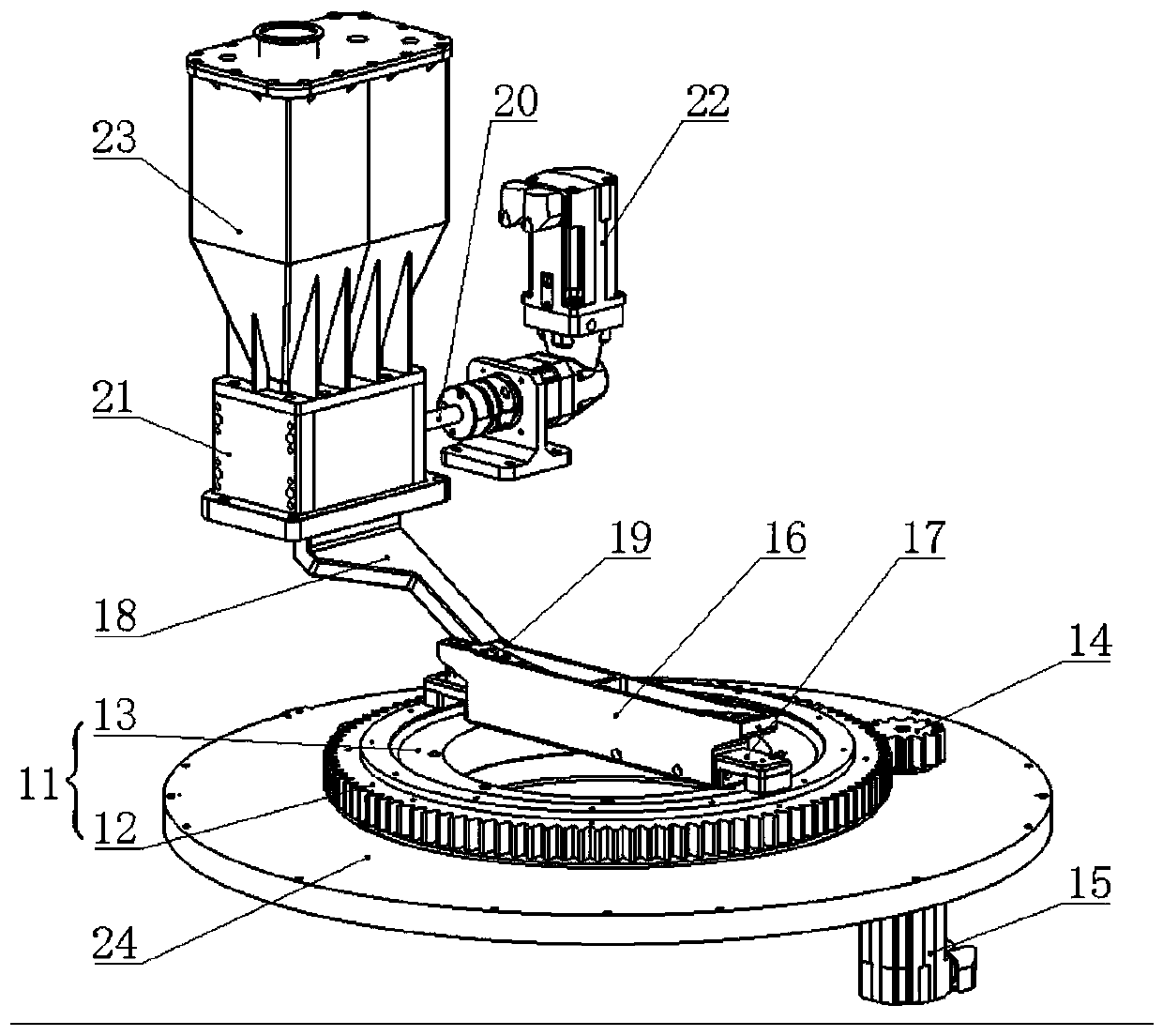
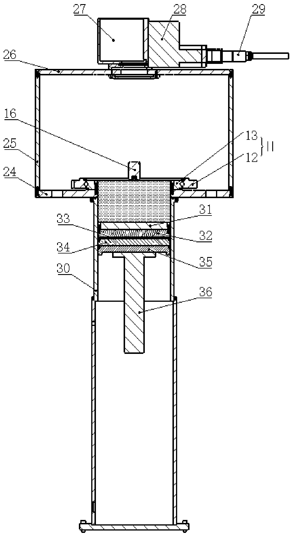
[0031] Such as Figure 2 to Figure 6 As shown, a continuous circulation powder spreading structure includes a powder spreading scraper 16, a gear bearing 11 and a platen 24, and a forming through hole is provided in the middle of the gear bearing 11 and the platen 24, and the gear bearing 11 includes an outer ring 12 and a nested The inner ring 13 that can rotate relative to the outer ring in the outer ring 12, the inner ring 13 is fixed on the upper end of the table 24, the powder spreading scraper 16 is fixed on the upper end of the outer ring 12, the outer ring 12 is provided with transmission teeth in the circumferential direction, and the table 24 is equipped with The printing substrate 31 formed on the part; the upper end of the powder spreading scraper 16 is provided with a buffer powder bin, and the buffer powder bin is provided with a deflector 19, and the def...


PUM


Abstract

The invention discloses a continuous cyclic powder spreading structure and additive manufacturing molding equipment. Side plates and a top plate are arranged on a bedplate. A printing molding cavity is formed by the bedplate and a cylinder body arranged at the lower end of the bedplate. The continuous cyclic powder spreading structure is arranged in the printing molding cavity, and continuous powder spreading in the printing molding process is achieved. Up-and-down movement of a printing substrate in the cylinder body is achieved by utilizing a driving device. Then the printing surface on theprinting substrate is printed and molded by utilizing a light path scanning structure arranged at the inner upper end of the printing molding cavity. Molding through holes are formed in a gear bearingand the middle of the bedplate correspondingly so that it is convenient for light path scanning structure laser and the printing surface on the printing substrate at the lower end of the bedplate tomold. The light path scanning structure is located at the upper end of the continuous cyclic powder spreading structure and can work simultaneously with a powder spreading scraper so that powder spreading and scanning molding are conducted, and that is to say, an efficient printing process that powder spreading is conducted while scanning is conducted can be achieved. By means of the continuous cyclic powder spreading structure and the additive manufacturing molding equipment, molding efficiency of parts is improved; and meanwhile, the printing substrate moves up and down in the cylinder body,the molding area is limited, and the utilization rate of powder is improved.

Description

technical field [0001] The invention belongs to the field of additive manufacturing equipment, and in particular relates to a continuous circulation powder spreading structure and additive manufacturing forming equipment. Background technique [0002] Additive manufacturing technology integrates multi-disciplinary technologies such as new materials, information and manufacturing. It is known as a representative technology that is expected to produce the "third industrial revolution" and is a leading technology for the development of mass manufacturing mode to personalized manufacturing mode. As the most cutting-edge and most potential technology in the entire additive manufacturing system, metal additive manufacturing technology is an important development direction of advanced manufacturing technology. It is suitable for the near-net shape of complex components. The formed parts manufactured by additive manufacturing technology have excellent mechanical properties, are suit...

Claims


Application Information

Patent Timeline
IPC IPC(8): B22F3/105B33Y30/00
CPCB33Y30/00B22F10/00B22F12/44B22F12/49B22F10/28Y02P10/25
Inventor 陈祯邹亚桐张树哲卢秉恒赵纪元韦继翀刘亮魏培
Owner NAT INST CORP OF ADDITIVE MFG XIAN
Learn More