
Six-bar mechanism multi-foot robot and modeling method thereof

A technology of multi-legged robot and six-bar mechanism, which is applied in the field of six-bar mechanism multi-legged robot and its modeling, can solve the problems of long claws, large volume, and inability to meet the requirements of narrow space operations, and achieve good rigidity and force transmission. Superior performance, satisfying the effect of working in a narrow space

Pending Publication Date: 2019-12-13
LULIANG UNIV
View PDF0 Cites 7 Cited by
  • Summary
  • Abstract
  • Description
  • Claims
  • Application Information

AI Technical Summary

Problems solved by technology

[0005] The purpose of the present invention is to provide a multi-legged robot with a six-bar mechanism and its modeling method. The present invention uses two sets of DC motors to drive two sets of leg mechanisms. The staggered movement of the claws, the six-bar mechanism can change the extension range of the feet and then change the extension length, and arbitrarily change the crawling mode of the robot. The staggered movement of adjacent six-bar mechanisms realizes the walking of the robot. The assembly is compact and can meet the needs of narrow space operations. Requirements, can solve the problems in the prior art that the feet are long and the volume is large, which cannot meet the requirements of narrow space operations

Method used


Image

  • Six-bar mechanism multi-foot robot and modeling method thereof
  • Six-bar mechanism multi-foot robot and modeling method thereof
  • Six-bar mechanism multi-foot robot and modeling method thereof

Examples


Embodiment Construction

[0049] The following will clearly and completely describe the technical solutions in the embodiments of the present invention with reference to the accompanying drawings in the embodiments of the present invention. Obviously, the described embodiments are only some, not all, embodiments of the present invention. Based on the embodiments of the present invention, all other embodiments obtained by persons of ordinary skill in the art without making creative efforts belong to the protection scope of the present invention.

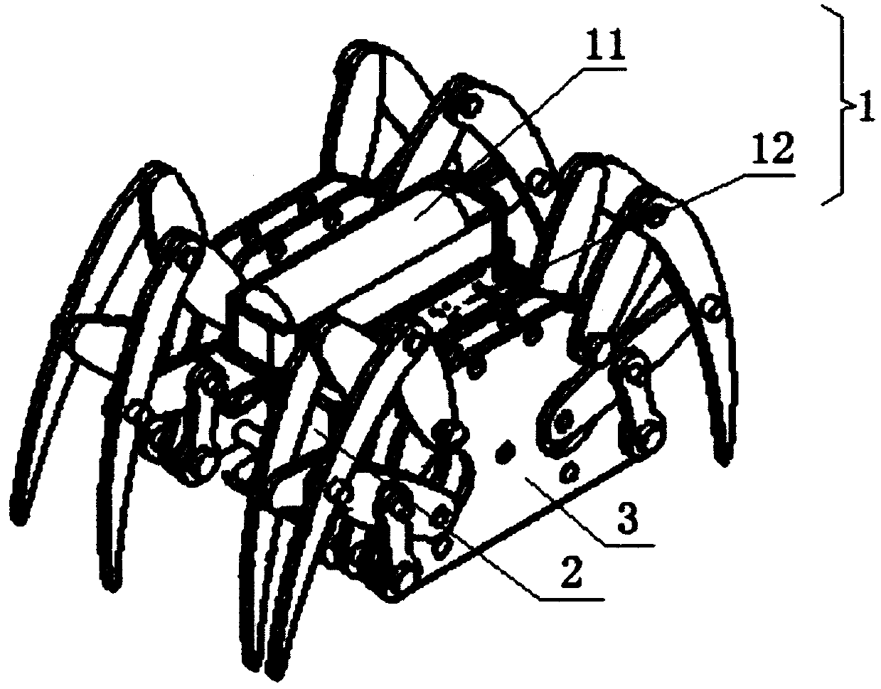
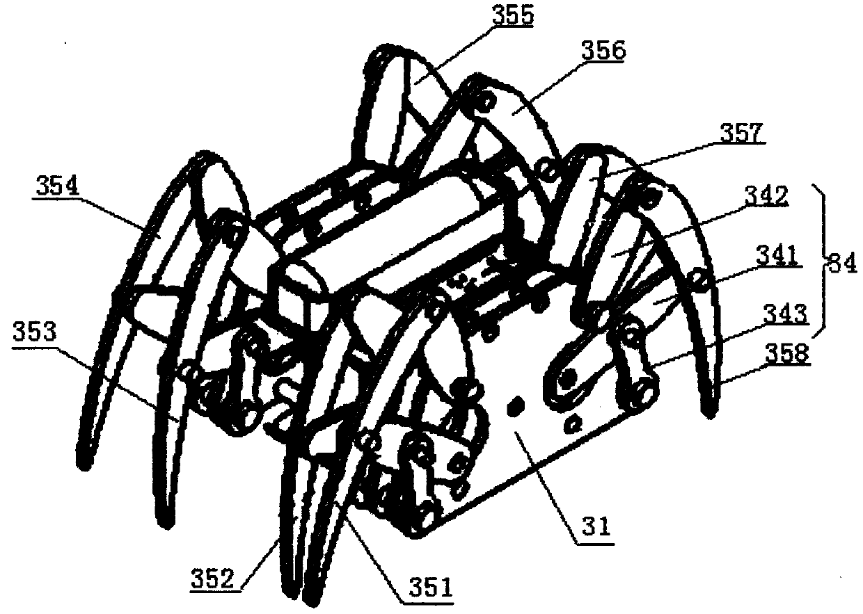
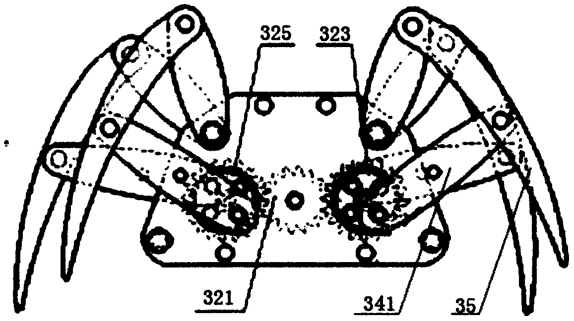
[0050] see figure 1 , a multi-legged robot with a six-bar mechanism, including a control device 1, a bevel gear reducer 2 and a left-right symmetrical leg mechanism 3, a control device 1 is installed between the two leg mechanisms 3, and the control device 1 is composed of a power supply 11, a built-in The controller 12 of the DC motor control board, the DC motor A13 and the DC motor B14 are composed. The controller 12 is electrically connected to the DC motor...


PUM


Abstract

The invention discloses a six-bar mechanism multi-foot robot and a modeling method thereof. The six-bar mechanism multi-foot robot comprises a control device, bevel gear speed reducers and left-rightsymmetrical leg mechanisms, wherein the control device is composed of a power supply, a controller internally provided with a direct-current motor control board, a direct-current motor A and a direct-current motor B, and the output shafts of the direct-current motor A and the direct-current motor B are correspondingly connected to the bevel gear speed reducers; and each leg mechanism consists of shell plates, a gear transmission assembly A, a gear transmission assembly B, a six-bar mechanism and a foot claw assembly, and in the case of each leg mechanism, the gear transmission assembly A is mounted between the two shell plates, and the gear transmission assembly B is mounted between the other two shell plates, and both the gear transmission assembly A and the gear transmission assembly B drive the foot claw assembly through the six-bar mechanism. According to the six-bar mechanism multi-foot robot and the modeling method thereof, the two leg mechanisms are driven by the two direct-current motors, the six-bar mechanisms push eight foot claws of front and rear groups to move in a staggered mode, so that walking of the robot is achieved through the staggered movement of the adjacent six-bar mechanisms; and assembling of the robot is compact, thus meeting the requirements of narrow-space operation.

Description

technical field [0001] The invention relates to a six-bar mechanism multi-leg robot, in particular to a six-bar mechanism multi-leg robot and a modeling method thereof. Background technique [0002] Robot technology is one of the major achievements of science and technology, and it has been widely used in industrial technology, national defense and military and other technical fields. With the advancement of science and technology, the research of robots is not limited to fixed-point operations in structured environments, but more towards the direction of unstructured environments, which requires robots to have the ability to adapt to unstructured environments and autonomy. [0003] As we all know, most of the current survey, inspection, and reconnaissance robots move in wheeled or crawler-type, and the wheeled mobile mechanism is highly dependent on the terrain, which is not suitable for rough terrain operations, and not only loses the advantage of low energy consumption o...

Claims


Application Information

Patent Timeline
IPC IPC(8): B62D57/032G06F17/50
CPCB62D57/032
Inventor 李晋张林
Owner LULIANG UNIV
Learn More