Cross-space ladder

A main frame and operating system technology, applied in the field of moving ladders across the air, can solve the problems of long walking distance, inconvenience to the disabled, physical exertion, etc., achieve low manufacturing and maintenance costs, save time and energy, and occupy a small area Effect

Active Publication Date: 2019-12-13
陈世记
View PDF7 Cites 0 Cited by
  • Summary
  • Abstract
  • Description
  • Claims
  • Application Information

AI Technical Summary

Problems solved by technology

[0004] In view of the above technical problems, the embodiment of the present invention provides a high-efficiency, fast, easy-to-use and easy-to-use air-span moving ladder, which can directly transport pedestrians from one side of the road to the other side, so as to solve the problem of the long walking distance of existing human-shaped overpasses. , time-consuming, labor-intensive, and inconvenient for the disabled and pedestrians with walking difficulties

Method used


Image

  • Cross-space ladder
  • Cross-space ladder
  • Cross-space ladder

Examples


Embodiment 1

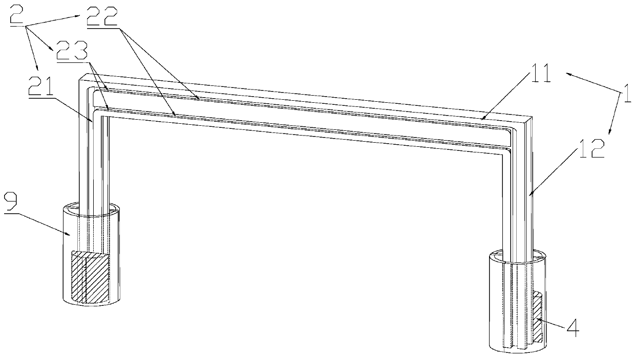
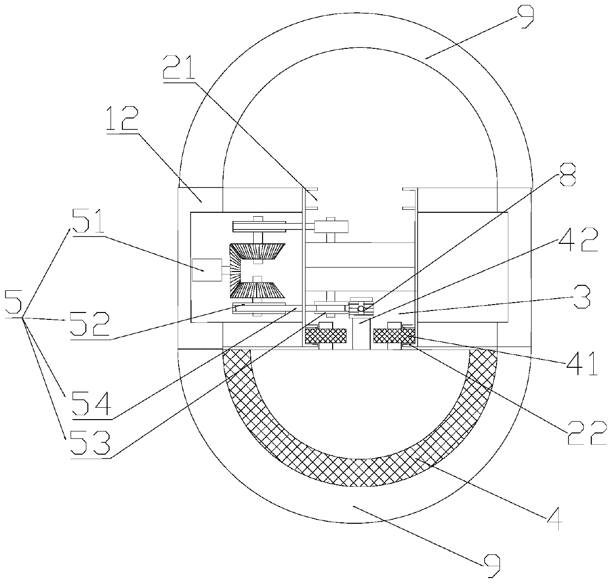
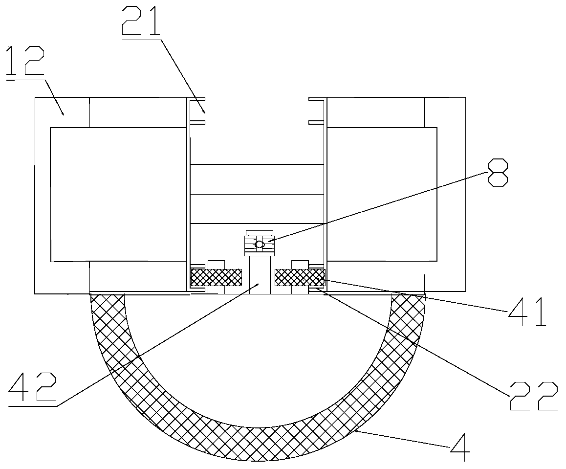
[0039] Such as Figure 1-5 A kind of moving ladder is shown, which includes a main frame 1 for crossing both sides of the road surface, and a manned running system arranged along the main frame. The main frame 1 includes a beam 11 and columns 12 fixed on both sides of the beam. , the whole is an inverted U-shaped structure.

[0040] The manned running system includes a sliding guide rail 2 located on the main frame, a traction guide rail 3 , a passenger cabin 4 and a traction mechanism 5 for carrying people running along the sliding guide rail. The sliding guide rail 2 is positioned at the U-shaped side of the main frame, extends from one end of the main frame 1 to the other end, and it consists of a horizontal guide rail 21, two vertical guide rails 22 positioned on both sides of the horizontal guide rail, and connecting the horizontal guide rail 21 and the vertical guide rail 22 arc guide rail 23 constitutes. Each section of the guide rails of the traction guide rail 3 is ...

Embodiment 2

[0055] In this embodiment, on the basis of Embodiment 1, the winding part of the traction mechanism is replaced by a chain, which is meshed with the traction wheel and the guide wheel, and the guide wheel and the guide wheel are gears. This traction mechanism has higher transmission efficiency, more stable operation and higher cost.

[0056] The two manned running systems are independently driven by their respective traction mechanisms 5, and the two manned cabins operate independently under the action of their respective manned running systems. The driving machines of the two sets of manned running systems and the traction wheels connected to them are respectively set in the inner cavity at the bottom of the two columns, which not only makes full use of the inner cavity structure of the two columns, but also reduces the occupied area of ​​the columns, making it Easier to popularize. The independent setting of the above two manned operating systems also improves the flexibili...


PUM


Abstract

The invention discloses a cross-space ladder. The ladder comprises a main body frame used for crossing two sides of a road surface and a manned operation system arranged along the main body frame, wherein the main body frame comprises a cross beam and stand columns fixedly arranged on the two sides of the cross beam, and the manned operation system comprises a sliding guide rail located on the main body frame, a traction guide rail, a manned small cabin moving along the sliding guide rail and a traction mechanism; the sliding guide rail is located on the side surface of the main body frame andcomprises a horizontal guide rail, two vertical guide rails located on two sides of the horizontal guide rail, and arc guide rails connecting the horizontal guide rail with the vertical guide rails;and a sliding wheel set matched with the sliding guide rail and a traction connecting part connected with the traction mechanism are arranged on the back surface of the manned small cabin, and the traction mechanism drives the manned small cabin to run from the bottom of the stand column on one side to the bottom of the stand column on the other side along the sliding guide rail. The cross-space ladder is compact in structure and small in occupied area, pedestrians can quickly, conveniently and fast cross a space from one side to the other side, and people who are disabled and has difficulty in walking can conveniently pass the road.

Description

technical field [0001] The invention relates to the technical field of elevators, in particular to a moving elevator across the sky. Background technique [0002] At present, the competition between pedestrians and vehicles on urban roads has seriously affected the speed of vehicles and brought serious personal safety threats to pedestrians. The pedestrian crossings set at important intersections not only aggravate traffic congestion, but also bring many inconveniences to pedestrians crossing the street, such as Waiting for traffic lights takes a long time, there are safety hazards, and it is not suitable for the disabled and the elderly with walking difficulties. In addition, both sides of railways and expressways are impassable for long distances. Although the existing pedestrian bridges solve the above problems to a certain extent, the existing pedestrian bridges occupy a large area and greatly prolong the walking distance of pedestrians crossing the street. Pedestrians...

Claims


Application Information

Patent Timeline
Patent Type & Authority Applications(China)
IPC IPC(8): B66B9/00B66B11/08
CPCB66B9/003B66B11/0095
Inventor 曾智勇
Owner 陈世记
Why Eureka
Try Eureka