Inspection well installation structure and construction method

A technology of installation structure and construction method, applied in infrastructure engineering, underwater structures, excavation, etc., can solve the problems affecting the safety of vehicles and pedestrians, sinking site, loose roadbed, etc., to reduce settlement, increase stability, The effect of reducing the impact

Active Publication Date: 2019-12-13
中基华工程管理集团有限公司
View PDF7 Cites 2 Cited by
  • Summary
  • Abstract
  • Description
  • Claims
  • Application Information

AI Technical Summary

Problems solved by technology

When backfilling the roadbed during the installation of the inspection well, the roadbed around the inspection well is relatively loose because the compaction machine cannot approach the surroundings of the inspection well at close range for compaction. The pavement structure will gradually sink, and under the action of vehicles and pedestrians, the road surface around the manhole cover will sink and crack, which will affect the safety of vehicles and pedestrians.

Method used


Image

  • Inspection well installation structure and construction method

Examples


Embodiment Construction

[0041] The present invention will be described in further detail below in conjunction with the accompanying drawings and embodiments.

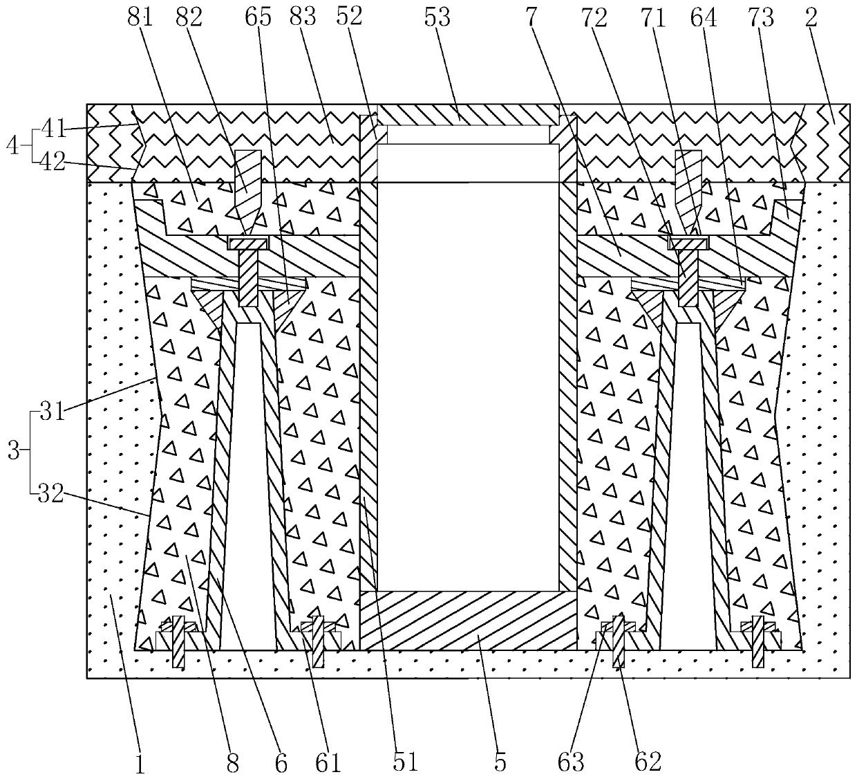
[0042] An installation structure for an inspection well, such as figure 1As shown, the installation structure is used to install the inspection well 51 on the road base 1 , and the top surface of the road base 1 is laid with an asphalt pavement 2 . The installation structure includes a first foundation pit 3 and a second foundation pit 4. The first foundation pit 3 is set on the subgrade 1. The first foundation pit 3 includes a first upper foundation pit 31, a first lower foundation pit 32, and a first lower foundation pit 3. The inner side wall of the foundation pit 32 is set on a conical surface, and the angle between the inner side wall of the first lower foundation pit 32 and the vertical plane is 10°, the first upper foundation pit 31 is located above the first lower foundation pit 32, and the first upper foundation pit 32 The inner side...


PUM


Abstract

The invention relates to an inspection well installation structure and construction method, and belongs to the technical field of inspection well construction. The structure comprises a first foundation pit, a second foundation pit and a base arranged in the first foundation pit, wherein an inspection well is arranged on the base, a well seat is arranged at the top end of the inspection well, a well cover is arranged on the well seat, a plurality of stand columns are arranged between the inspection well and the side wall of the first foundation pit, pressure bearing rings are detachably arranged at the top ends of the stand columns, a lower foundation soil layer is arranged below the pressure bearing rings and arranged between the side wall of the first foundation pit and the outer peripheral surface of the inspection well, an upper foundation soil layer is arranged above the pressure bearing rings and arranged between the side wall of the first foundation pit and the outer peripheralsurface of the inspection well, and an asphalt layer is arranged between the well seat and the second foundation pit. According to the structure and the method, the thickness of the upper foundation soil layer above the pressure bearing rings is relatively thin, so that the upper foundation soil layer can be easily compacted, and when the lower foundation soil layer below the pressure bearing rings settles, the pressure bearing rings do not settle along with the lower foundation soil layer under the supporting effect of the stand columns, so that the phenomenons of settling and cracking of pavements surrounding the well cover is reduced.

Description

technical field [0001] The invention relates to the technical field of inspection well construction, in particular to an installation structure of an inspection well and a construction method thereof. Background technique [0002] The inspection well is set up for the convenience of installation and maintenance of the power supply, water supply, drainage, communication and other lines of the underground infrastructure. At a certain distance, it is convenient for regular inspection of ancillary structures. When backfilling the roadbed during the installation of the inspection well, the roadbed around the inspection well is relatively loose because the compaction machine cannot approach the surroundings of the inspection well at close range for compaction. The pavement structure will gradually sink, and then under the action of vehicles and pedestrians, the road surface around the manhole cover will sink and crack, which will affect the safety of vehicles and pedestrians. C...

Claims


Application Information

Patent Timeline
Patent Type & Authority Applications(China)
IPC IPC(8): E02D29/12E02D17/06E02D17/08E02D17/12
CPCE02D17/06E02D17/08E02D17/083E02D17/12E02D29/12E02D29/125
Inventor 王睿卓崔亦杰
Owner 中基华工程管理集团有限公司
Why Eureka
Try Eureka