Advance grouting transformation method of bottom plate combination directional holes of deeply-buried aquifers underground coal mine

A technology of floor combination and advanced grouting, which is applied in drilling equipment and methods, directional drilling, wellbore lining, etc., can solve the problems of high drilling cost, difficulty in depressurizing water drainage, and unsatisfactory mining conditions under pressure. The effect of safe and efficient hole forming and high governance efficiency

Active Publication Date: 2019-12-13
XIAN RES INST OF CHINA COAL TECH& ENG GROUP CORP
View PDF9 Cites 14 Cited by
  • Summary
  • Abstract
  • Description
  • Claims
  • Application Information

AI Technical Summary

Problems solved by technology

[0006] The purpose of the invention is to prevent and control water hazards in deep underground multi-aquifer floors of coal mines, where drainage and pressure reduction are difficult, mining conditions under pressure are not available, conventional grouting reconstruction drilling costs are high, and conventional directional holes are only suitable for single aquifer reconstruction. There are deficiencies such as governance blind areas, and a method for advanced grouting reconstruction of combined directional holes in the bottom plate of deeply buried aquifers in coal mines is provided

Method used


Image

  • Advance grouting transformation method of bottom plate combination directional holes of deeply-buried aquifers underground coal mine
  • Advance grouting transformation method of bottom plate combination directional holes of deeply-buried aquifers underground coal mine
  • Advance grouting transformation method of bottom plate combination directional holes of deeply-buried aquifers underground coal mine

Examples


Embodiment

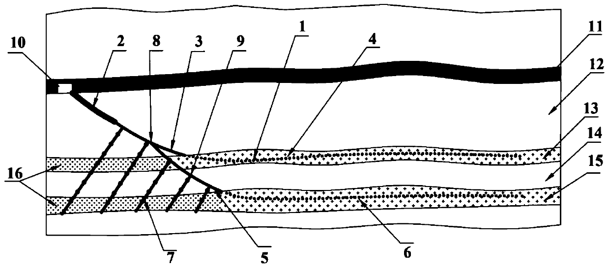
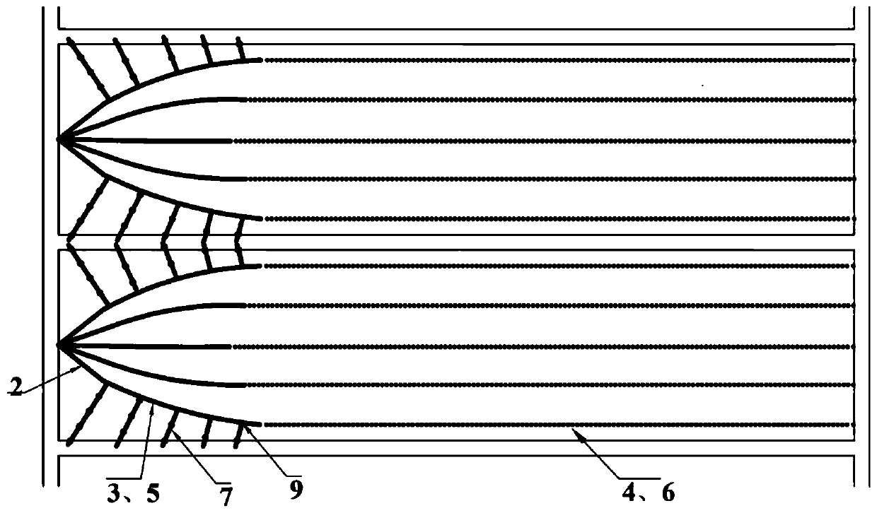
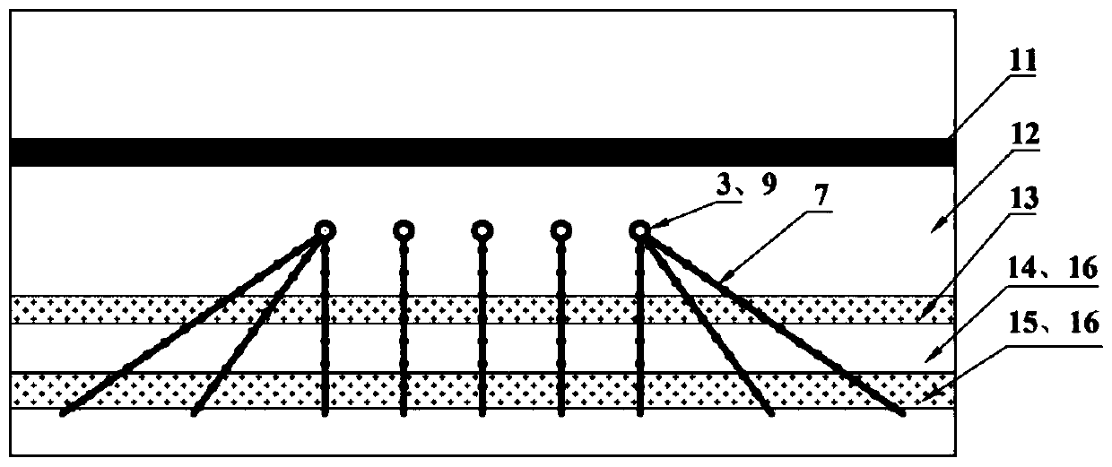
[0035] see figure 1 Combination directional hole 1 in the advanced grouting reconstruction method of deep buried aquifer bottom plate combined directional hole in coal mine is composed of casing hole section 2, upper deflection hole section 3, upper horizontal hole section 4, lower deflection hole section 5, lower The horizontal hole section 6 and the jet hole section 7 are composed. The above whipped hole section 3 is reserved with a directional branch point 8 and a jet flow branch point 9 .

[0036] The method for advanced grouting reconstruction of deep-buried aquifer bottom plate combined directional holes in underground coal mines comprises the following steps:

[0037] Step 1: Construction of the casing hole section. In the set drilling site 10, holes are drilled from the coal seam 11 to the lower side, and after the construction is carried out to the designed position with the full-eye rotary straight drilling tool, the casing is lowered, and then cement slurry is inj...


PUM


Abstract

The invention relates to an advance grouting transformation method of bottom plate combination directional holes of deeply-buried aquifers underground a coal mine. The advance grouting transformationmethod includes the steps that the bottom plate combination directional holes are constructed, and comprise deflecting hole sections entering the aquifers from aquicludes and horizontal hole sectionsstarting from the deflecting hole sections and extending inside the aquifers; jet hole sections penetrating through one or more of the aquifers in an extending mode are constructed on the side walls of the deflecting hole sections at the preset interval, and the jet hole sections do not intersect with the horizontal hole sections in the aquifers and cover blind areas of the horizontal hole sections; and grouting is conducted on the horizontal hole sections and the jet hole sections to transform aquifer bottom plates into aquiclude bottom plates. According to the advance grouting transformationmethod, the problems that the distance from a coal seam is large, the number of the aquifers is large, the treatment effect of the coal seam bottom plates with the high water pressure is poor, the blind areas are prone to existing are solved, the advantages that the grouting covering area is wide, no blind area exists in treatment, and efficiency is high are achieved, advance area grouting transformation of the bottom plates of the multiple deeply-buried aquifers is achieved, and the technical guarantee is provided for safe stoping of a working face.

Description

technical field [0001] The invention relates to a grouting reconstruction method, which belongs to the field of coal mine water disaster prevention and control, in particular to a method for advance grouting reconstruction with combined directional holes in the deep buried aquifer bottom plate of a coal mine. Background technique [0002] Water damage is one of the five major natural disasters in coal mines in my country. Floor water damage is one of the main types of coal mine water damage. Its water inrush pressure is high, the flow rate is large, and it is destructive, which brings serious safety hazards to coal mine production. Especially with the gradual development of coal mining to the deep, the pressure of the confined water on the floor, the number of aquifers, the water volume and the buried depth gradually increase, and the threat to the mine is becoming more and more serious. [0003] At present, the methods of drainage and depressurization, under pressure minin...

Claims


Application Information

Patent Timeline
Patent Type & Authority Applications(China)
IPC IPC(8): E21B7/04E21B7/06E21B33/13E21D11/10E21D11/38
CPCE21B7/04E21B7/06E21B7/065E21B33/13E21D11/10E21D11/38
Inventor 方俊李泉新石智军许超刘飞刘建林王鲜
Owner XIAN RES INST OF CHINA COAL TECH& ENG GROUP CORP
Why Eureka
Try Eureka