
Flange for plastic processing exhaust gas transmission

A technology using flanges and exhaust gas, which is applied in flange connections, pipeline heating/cooling, pipes/pipe joints/fittings, etc., can solve the problems of pipeline blockage, waste liquid cannot be removed, and high energy consumption, so as to reduce energy consumption, The effect of simple structure and low cost

Inactive Publication Date: 2019-12-13
徐州顶峰机械制造有限公司
View PDF2 Cites 0 Cited by
  • Summary
  • Abstract
  • Description
  • Claims
  • Application Information

AI Technical Summary

Problems solved by technology

[0004] The main purpose of the present invention is to provide a flange for transporting waste gas from plastic processing, which solves the problems that the current flange installation cannot be heated, the pipeline is blocked, the waste liquid cannot be discharged, and the energy consumption is high.

Method used


Image

  • Flange for plastic processing exhaust gas transmission
  • Flange for plastic processing exhaust gas transmission
  • Flange for plastic processing exhaust gas transmission

Examples


Embodiment 1

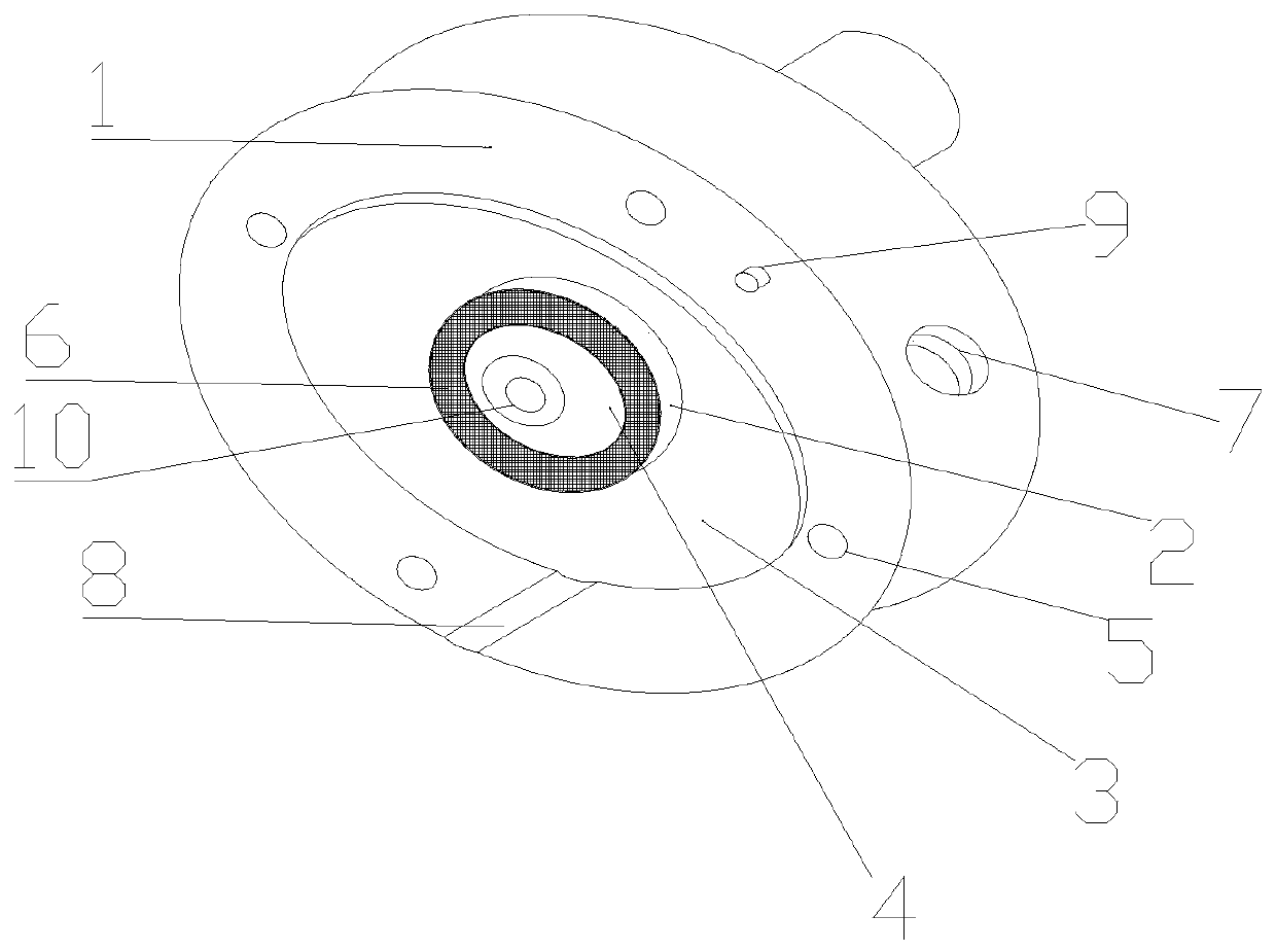
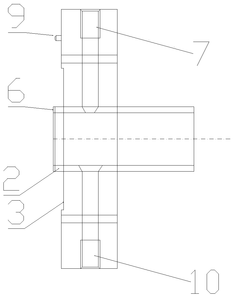
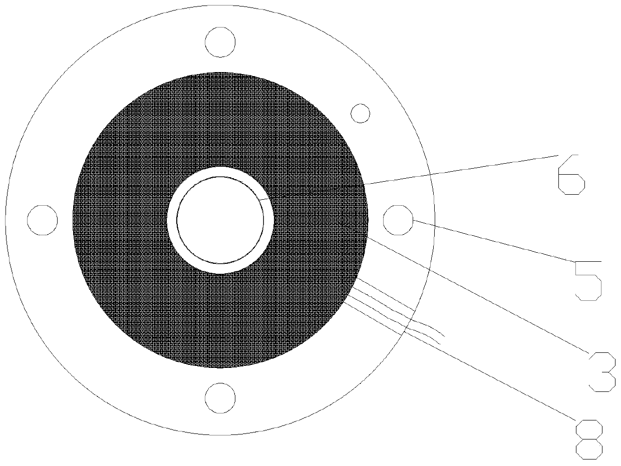
[0025] refer to Figure 1-Figure 3 As shown, a flange used for conveying waste gas from plastic processing is composed of a flange shell 1, a boss 2, a heating groove 3, a through hole 4, a bolt hole 5, a ring groove 6, a temperature measuring hole 7, and a wire groove 8. The positioning pin 9 and the waste discharge hole 10 are formed. The through hole 4 is located in the center of the flange shell 1; the boss 2, the heating groove 3, the wire groove 8, and the positioning pin 9 are located on the flange assembly surface; the height of the boss 2 is greater than The height of the positioning pin 9, the end surface of the boss 2 is provided with a circular groove 6 for placing the sealing ring; the bolt holes 5 are symmetrically and evenly distributed on the flange shell 1 for the assembly of the flange; the heating groove 3 is a circular ring shape, located between the through hole 4 and the bolt hole 5; the temperature measuring hole 7 and the waste discharge hole 10 are set...

Embodiment 2

[0035] refer to Figure 1-Figure 3 As shown, a flange used for conveying waste gas from plastic processing is composed of a flange shell 1, a boss 2, a heating groove 3, a through hole 4, a bolt hole 5, a ring groove 6, a temperature measuring hole 7, and a wire groove 8. The positioning pin 9 and the waste discharge hole 10 are formed. The through hole 4 is located in the center of the flange shell 1; the boss 2, the heating groove 3, the wire groove 8, and the positioning pin 9 are located on the flange assembly surface; the height of the boss 2 is greater than The height of the positioning pin 9, the end surface of the boss 2 is provided with a circular groove 6 for placing the sealing ring; the bolt holes 5 are symmetrically and evenly distributed on the flange shell 1 for the assembly of the flange; the heating groove 3 is a circular ring shape, located between the through hole 4 and the bolt hole 5; the temperature measuring hole 7 and the waste discharge hole 10 are set...


PUM


Abstract

The invention relates to a flange for plastic processing exhaust gas transmission. The flange is composed of a flange housing, a boss, a heating groove, a through hole, bolt holes, a ring groove, a temperature measuring hole, a wire groove, a positioning pin and a waste discharging hole. The through hole is located in the center of the flange housing; the boss, the heating groove, the positioningpin and the wire groove are located on the flange assembly surface; the height of the boss is greater than the height of the positioning pin, and the boss end face is provided with the ring groove tobe used for containing a sealing ring; the bolt holes are symmetrically distributed in the flange housing to be used for flange assembling; the heating groove is ring-shaped and is located between thethrough hole and the bolt holes; and the temperature measuring hole and waste discharging hole are arranged in the radial direction of the flange housing and are half-threaded through hole. The flange has the beneficial effect that the problems that an existing flange cannot be heated, a pipeline is blocked, waste liquid cannot be discharged, and the energy consumption is high are solved.

Description

technical field [0001] The invention belongs to the technical field of pipe connectors, in particular to a flange, and more specifically to a flange for conveying waste gas from plastic processing. Background technique [0002] Flange as the middleware of pipeline connection is a very common application of pipeline connection. Flange connection is to fix two pipes, pipe fittings or equipment on a flange plate first, add flange pads between the two flange plates, and fasten them with bolts to complete the connection. [0003] During the plastic processing process, a large amount of waste gas is generated due to the decomposition of plastic, and the melting points of the components in the waste gas are different. Therefore, during the transportation of these waste gases, as the temperature of the pipeline gradually decreases, solidification will form on the pipe wall, especially the flange. The utility model patent with application number 201510267382.9 is a heatable flange, ...

Claims


Application Information

Patent Timeline
Patent Type & Authority Applications(China)
IPC IPC(8): F16L23/032F16L23/00F16L23/18F16L53/38F16L55/24
CPCF16L23/006F16L23/032F16L23/18F16L53/38F16L55/24
Inventor 刘斌
Owner 徐州顶峰机械制造有限公司
Learn More