
Photoelectric reflective information sensor

A sensor and reflective technology, which is applied in the field of photoelectric sensing, can solve the problems of photoelectric reflective information sensors, which are difficult to miniaturize electronic products, require a large investment, and are not beautiful enough, and achieve the effects of detecting weak information and reducing the horizontal area

Pending Publication Date: 2019-12-13
SHENZHEN HUAJING BAOFENG ELECTRONICS
View PDF0 Cites 0 Cited by
  • Summary
  • Abstract
  • Description
  • Claims
  • Application Information

AI Technical Summary

Problems solved by technology

[0002] There are following defects in the present photoelectric type reflective information sensor: 1. need to make very thick shading object 53 (such as Figure 5 As shown), plus the process space that needs to be considered when installing the light-emitting device 51 and the photosensitive device 52, it will occupy a large area, resulting in the photoelectric reflective information sensor cannot be made into a small-volume device, making it difficult to use the photoelectric reflective information sensor On miniature electronic products (such as wearable or handheld electronic products)
2. Since the light-emitting device 51 and the photosensitive device 52 are far apart, a considerable part of the light emitted by the light-emitting device is ineffective (reflected light is not irradiated on the photosensitive device), and the utilization rate of light is low
In this case, the structure is complicated and the investment is large, and the product cost is high
3. In order to meet the needs of aesthetics, waterproofing, etc. of electronic products, it is often necessary to install a lens on the corresponding housing 54 of the sensor. Since it is necessary to perform optical isolation between the light-emitting device and the photosensitive device, it is necessary to make an optical isolation coating on the lens. It is not beautiful enough and also increases the difficulty of handling

Method used


Image

  • Photoelectric reflective information sensor
  • Photoelectric reflective information sensor
  • Photoelectric reflective information sensor

Examples


Embodiment 1

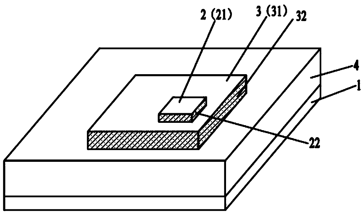
[0030] like figure 1 As shown, the photoelectric reflective information sensor provided in Embodiment 1 includes a substrate 1 provided with electrical connection lines, a light-emitting device 2 and a photosensitive device 3, and the other surfaces of the light-emitting device 2 except the light-emitting surface 21 are coated with the first A light-shielding layer 22, a second light-shielding layer 32 is coated on other surfaces of the photosensitive device 3 except the light-receiving surface 31, and the light-emitting device 2 coated with the first light-shielding layer 22 is coated with the second light-shielding layer. The photosensitive device 3 of the optical layer 32 is disposed on the substrate 1 , the remaining space on the substrate 1 is filled with a light-transmitting protective body 4 , and the light-transmitting protective body 4 surrounds the light-emitting device 2 and the photosensitive device 3 .

[0031] Wherein, the light-emitting device 2 is arranged on ...

Embodiment 2

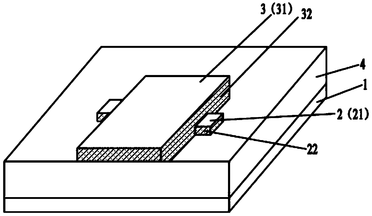
[0033] like figure 2 As shown, the photoelectric reflective information sensor provided in Embodiment 2 includes a substrate 1 provided with electrical connection lines, a light-emitting device 2 and a photosensitive device 3, and each surface of the light-emitting device 2 except the light-emitting surface 21 is coated with a first A light-shielding layer 22, a second light-shielding layer 32 is coated on other surfaces of the photosensitive device 3 except the light-receiving surface 31, and the light-emitting device 2 coated with the first light-shielding layer 22 is coated with the second light-shielding layer. The photosensitive device 3 of the optical layer 32 is disposed on the substrate 1 , the remaining space on the substrate 1 is filled with a light-transmitting protective body 4 , and the light-transmitting protective body 4 surrounds the light-emitting device 2 and the photosensitive device 3 .

[0034] Wherein, the light emitting device 2 and the photosensitive d...

Embodiment 3

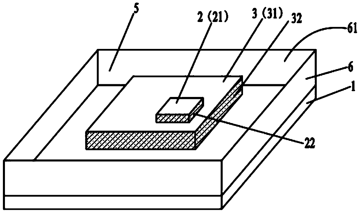
[0037] like image 3 As shown, the photoelectric reflective information sensor provided in Embodiment 3 includes a substrate 1 provided with electrical connection lines, a light-emitting device 2 and a photosensitive device 3, and each surface of the light-emitting device 2 except the light-emitting surface 21 is coated with a first A light-shielding layer 22, a second light-shielding layer 32 is coated on other surfaces of the photosensitive device 3 except the light-receiving surface 31, and the light-emitting device 2 coated with the first light-shielding layer 22 is coated with the second light-shielding layer. The photosensitive device 3 of the optical layer 32 is arranged on the substrate 1, the remaining space on the substrate 1 is filled with a light-transmitting colloid 5, and the light-transmitting colloid 5 surrounds the light-emitting device 2 and the photosensitive device 3, and a casing 6 is arranged around the light-transmitting colloid 5, Moreover, a light open...


PUM


Abstract

The invention discloses a photoelectric reflective information sensor. The sensor comprises a light-emitting device and a light-sensitive device. Other faces, except a light-emitting face, of the light-emitting device are coated with first light blocking layers, other faces, except a light-receiving face, of the light-sensitive device are coated with second light blocking layers, and the light-emitting device coated with the first light blocking layers and the light-sensitive device coated with the second light blocking layers are arranged in a contact mode or arranged at a set interval. The light-emitting device emits light from the light-emitting surface, the light is reflected by a detected object and then the light-receiving surface of the light-sensitive device is irradiated, and thedetection of the detected object is achieved. According to the invention, the horizontal area of the photoelectric reflective information sensor is reduced by 60-70%, a higher signal intensity / irradiation light intensity ratio can be obtained, and the energy consumption is reduced.

Description

technical field [0001] The invention relates to the technical field of photoelectric sensing, in particular to a photoelectric reflective information sensor. Background technique [0002] There are following defects in the present photoelectric type reflective information sensor: 1. need to make very thick shading object 53 (such as Figure 5 As shown), plus the process space that needs to be considered when installing the light-emitting device 51 and the photosensitive device 52, it will occupy a large area, resulting in the photoelectric reflective information sensor cannot be made into a small-volume device, making it difficult to use the photoelectric reflective information sensor Microelectronic products (such as wearable or handheld electronic products). 2. Since the light-emitting device 51 and the photosensitive device 52 are far apart, a considerable part of the light emitted by the light-emitting device is ineffective (reflected light does not irradiate the photose...

Claims


Application Information

Patent Timeline
Patent Type & Authority Applications(China)
IPC IPC(8): G01S17/02G01S17/06A61B5/0205A61B5/1455
CPCG01S17/06A61B5/0205A61B5/14552
Inventor 刘姣刘松涛张清海
Owner SHENZHEN HUAJING BAOFENG ELECTRONICS
Learn More