
Silicon controlled rectifier structure with multiple trigger channels

A silicon rectifier and trigger channel technology, applied in the electronic field, can solve the problems of high trigger voltage, high resistance, long DTSCR trigger time, etc., and achieve the effect of small trigger channel resistance, effective ESD protection, and device performance optimization.

Active Publication Date: 2019-12-13
UNIV OF ELECTRONICS SCI & TECH OF CHINA
View PDF3 Cites 0 Cited by
  • Summary
  • Abstract
  • Description
  • Claims
  • Application Information

AI Technical Summary

Problems solved by technology

[0011] like figure 2 As shown, among them, curve 1 is a schematic diagram of DTSCR current-voltage; the turn-on voltage of DTSCR is V on , the trigger voltage is V t1 , due to the large resistance of the trigger path, the current used to trigger the SCR path is small, which in turn causes the trigger voltage Vt1 to be higher than the turn-on voltage V on In a specific application circuit, due to the large difference between the trigger voltage and the turn-on voltage of DTSCR, the trigger time of DTSCR will be long and the trigger voltage will be high.
For a smaller design window, this undoubtedly increases the design complexity of ESD devices, so DTSCR devices cannot be used in low trigger voltage windows

Method used


Image

  • Silicon controlled rectifier structure with multiple trigger channels
  • Silicon controlled rectifier structure with multiple trigger channels
  • Silicon controlled rectifier structure with multiple trigger channels

Examples


Embodiment 1

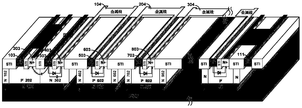
[0026] This embodiment provides a silicon-controlled rectifier structure with multiple trigger channels, and its device structure is as follows image 3 As shown, it consists of a diode string composed of 1 SCR device and n diodes, including:

[0027] The SCR device structure includes: a silicon substrate 100 of the first conductivity type; a deep well region 101 of the second conductivity type formed on the silicon substrate 100 of the first conductivity type, and in the deep well region of the second conductivity type The well region A of the second conductivity type adjacent from left to right formed in 101 1 102. Well region B of the first conductivity type 1 202. Well region A of the second conductivity type 2 302. Well region B of the first conductivity type 2 402 and the second conductivity type well region A 3 502, that is, the first conductivity type well region 202 is surrounded by the second conductivity type well region 102, the second conductivity type deep we...

Embodiment 2

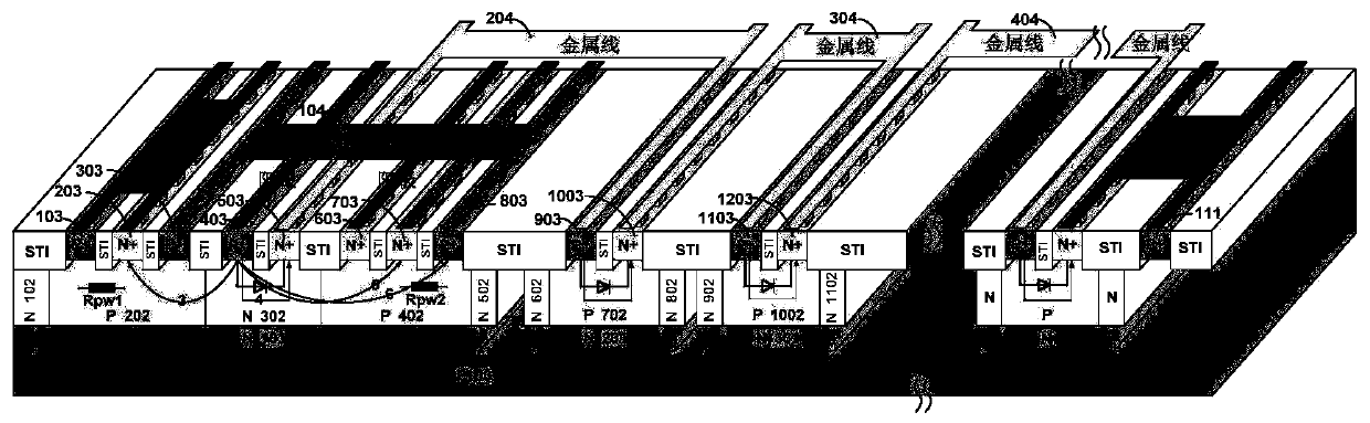
[0037] This embodiment provides a silicon-controlled rectifier structure with multiple trigger channels, and its device structure is as follows Figure 4 As shown, it is composed of a diode string composed of 1 SCR device and n diodes; the difference from Embodiment 1 is that the second conductivity type well region A 2 302 is provided with the second conductivity type heavily doped region D in sequence from left to right 2 503 and the first conductivity type heavily doped region C 3 403, the heavily doped region C of the first conductivity type 3 403 and the second conductivity type heavily doped region D 3 603 is connected to the anode of the device, and the heavily doped region D of the second conductivity type 2 503 is connected to the metal line 204 .

[0038] In this embodiment, compared with the device in Example 1, the improved multi-trigger channel silicon controlled rectifier structure exchanges the p-type heavily doped region 403 and the n-type heavily doped reg...


PUM


Abstract

The invention belongs to the technical field of electronics, and particularly relates to design of an ESD (Electro-Static discharge) protection circuit, in particular to a structure for jointly triggering a silicon controlled rectifier through a diode path, a triode path and an SCR path. Compared with the traditional diode single-trigger path, the silicon controlled rectifier structure with multiple trigger channels is additionally provided with the triode trigger path and the SCR trigger path, so that the trigger resistance is greatly reduced, the trigger current is effectively increased, thetrigger voltage is reduced, and the switch-on speed is higher; when an ESD event occurs, ESD pulse current can be effectively discharged.

Description

technical field [0001] The invention belongs to the field of electronic technology, and in particular relates to the design of an electrostatic discharge (ESD: Electro-Static discharge) protection circuit, especially a structure in which a silicon-controlled rectifier is jointly triggered by a diode path, a triode path, and an SCR path; specifically, a Silicon controlled rectifier structure with multiple trigger channels. Background technique [0002] Electro-Static discharge (ESD) phenomenon refers to the charge transfer phenomenon that occurs when objects with different potentials approach or contact each other. During the electrostatic discharge process, due to the extremely short discharge time, a large current will be generated. For integrated circuits, this high current can damage or even burn internal devices, resulting in chip failure. Electrostatic discharge may occur in all aspects of chip production, transportation and use, so ESD protection measures are very im...

Claims


Application Information

Patent Timeline
Patent Type & Authority Applications(China)
IPC IPC(8): H01L27/02H01L29/74
CPCH01L27/0262H01L29/7412
Inventor 刘继芝杨凯杜飞波刘志伟
Owner UNIV OF ELECTRONICS SCI & TECH OF CHINA
Learn More