High speed and high power permanent magnet synchronous motor rotor
A permanent magnet synchronous motor, high-power technology, applied to synchronous motors with stationary armatures and rotating magnets, magnetic circuit rotating parts, magnetic circuits, etc., can solve the problem of rotor sheath fitting and prestress cannot meet the needs Adjustment and other issues can be achieved to achieve the effect of simple structure, small torque fluctuation and improved torque density
- Summary
- Abstract
- Description
- Claims
- Application Information
AI Technical Summary
Problems solved by technology
Method used
Image
Examples
Embodiment 1
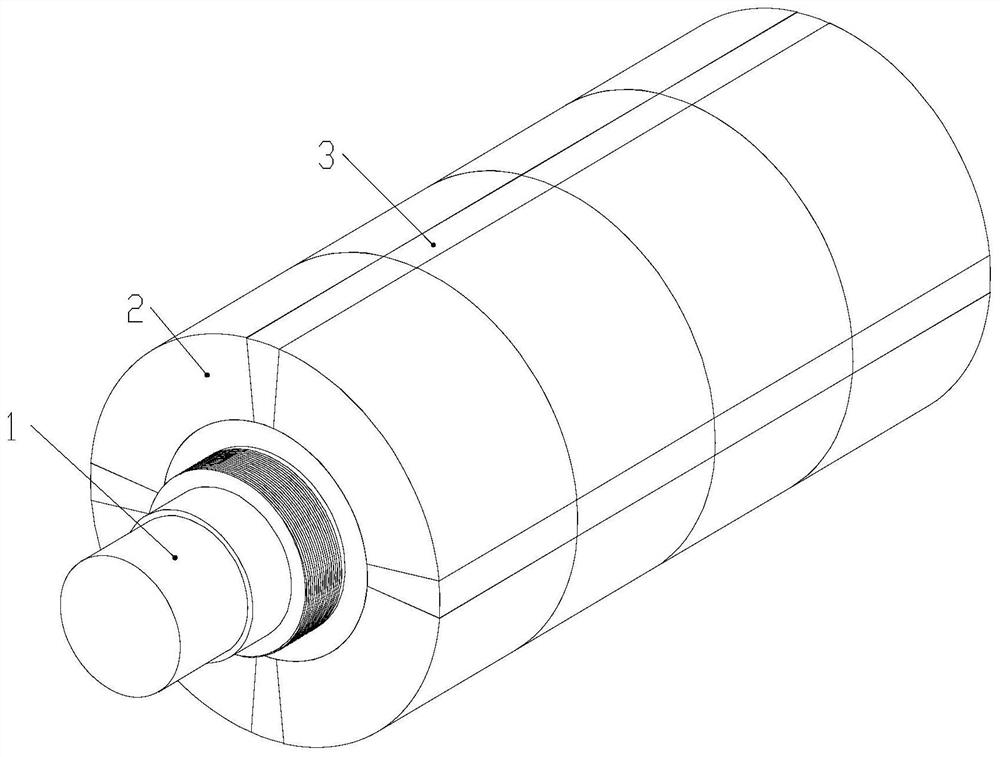
[0133] see figure 1 Describe the present embodiment 1, the high-speed and high-power permanent magnet synchronous motor rotor described in the present embodiment 1 includes a rotating shaft 1, a conical main permanent magnet 2, a conical auxiliary permanent magnet 3, a preload nut and a sheath;
[0134] The rotating shaft 1 is a cylindrical body tapered at both ends, and the two ends of the rotating shaft 1 are provided with external threads;
[0135] The taper of the inner surface of the tapered main permanent magnet 2 and the tapered auxiliary permanent magnet 3 is the same as the taper of the shaft body of the rotating shaft 1;
[0136] All the conical main permanent magnets 2 and all the conical auxiliary permanent magnets 3 are arranged on the outer surface of the rotating shaft 1, and form a cylindrical structure enclosing the shaft body of the rotating shaft 1, and along the circumferential direction, a total of 2P columns of main permanent magnets are formed Queues, e...
Embodiment 2
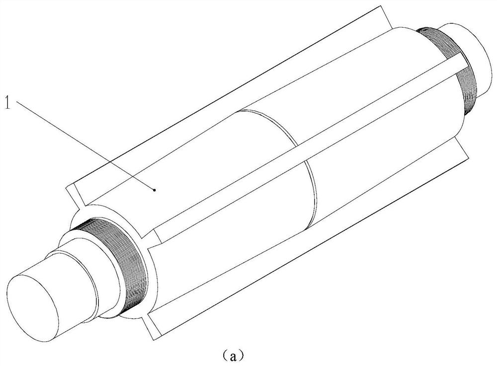
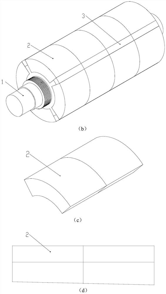
[0150] see figure 2 middle figure 2 a to figure 2 d illustrates this embodiment 2, the high-speed and high-power permanent magnet synchronous motor rotor described in this embodiment 2, including a rotating shaft 1, a conical main permanent magnet 2, an auxiliary permanent magnet 3, a preload nut and a sheath;
[0151] The rotating shaft 1 is a cylindrical structure, and its two ends are provided with external threads. The shaft body of the rotating shaft 1 in the circumferential direction is uniformly provided with 2P axial grooves, and each axial groove includes two main permanent magnet embedding grooves, two The main permanent magnet embedding grooves are mirror-symmetrically arranged on the vertical plane of the length of the shaft body, and the depth of each main permanent magnet embedding groove gradually increases from the vertical plane to the end of the shaft body, so that the shaft body of the shaft 1 is in the It tapers toward its two ends; P is the number of ...
Embodiment 3
[0167] see image 3 Describe this embodiment 3, the high-speed high-power permanent magnet synchronous motor rotor described in this embodiment 3 includes a rotating shaft 1, a conical main permanent magnet 2, an auxiliary permanent magnet 3, a positioning key 4, a preload nut and a sheath;
[0168] Rotating shaft 1 is a cylindrical body tapered at both ends, and both ends of rotating shaft 1 are provided with external threads, and 2P positioning key grooves are opened on the shaft of rotating shaft 1 along the axial direction, and P is the number of pole pairs of the motor;
[0169] The taper of the inner surface of the conical main permanent magnet 2 is the same as the taper of the shaft body of the rotating shaft 1;
[0170] A positioning key 4 is embedded in each positioning key groove, and 2k conical main permanent magnets 2 are arranged axially on the rotating shaft 1 between two adjacent positioning keys 4, where k is a positive integer;
[0171] The auxiliary permanen...
PUM
 Abstract
Description
Claims
Application Information
 - R&D
- Intellectual Property
- Life Sciences
- Materials
- Tech Scout
- Unparalleled Data Quality
- Higher Quality Content
- 60% Fewer Hallucinations
Browse by: Latest US Patents, China's latest patents, Technical Efficacy Thesaurus, Application Domain, Technology Topic, Popular Technical Reports.
© 2025 PatSnap. All rights reserved.Legal|Privacy policy|Modern Slavery Act Transparency Statement|Sitemap|About US| Contact US: help@patsnap.com


