Gate driving circuit and switching power source circuit

A technology of gate drive circuit and switching power supply circuit, which is applied in the direction of high-efficiency power electronic conversion, electrical components, and adjustment of electrical variables, and can solve the problems of full-load EMI and no-load standby power consumption.

Pending Publication Date: 2019-12-13
WUXI SI POWER MICRO ELECTRONICS
View PDF1 Cites 1 Cited by
  • Summary
  • Abstract
  • Description
  • Claims
  • Application Information

AI Technical Summary

Problems solved by technology

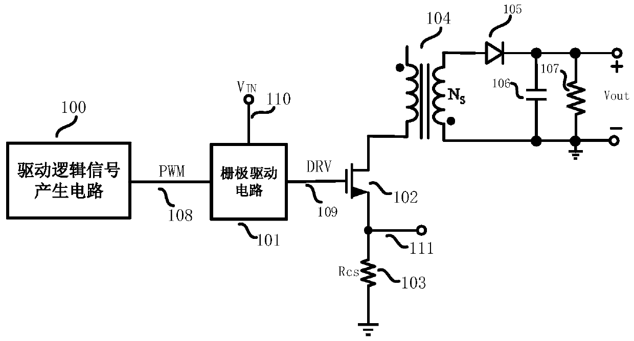
[0004] The present invention provides a gate drive circuit and a switching power supply circuit including the gate drive cir

Method used


Image

  • Gate driving circuit and switching power source circuit
  • Gate driving circuit and switching power source circuit
  • Gate driving circuit and switching power source circuit

Examples


Embodiment Construction

[0024] It should be noted that, in the case of no conflict, the embodiments of the present invention and the features in the embodiments can be combined with each other. The present invention will be described in detail below with reference to the accompanying drawings and examples.

[0025] In order to enable those skilled in the art to better understand the solutions of the present invention, the following will clearly and completely describe the technical solutions in the embodiments of the present invention in conjunction with the accompanying drawings in the embodiments of the present invention. Obviously, the described embodiments are only Embodiments of some, but not all, embodiments of the present invention. Based on the embodiments of the present invention, all other embodiments obtained by persons of ordinary skill in the art without making creative efforts shall fall within the protection scope of the present invention.

[0026] It should be noted that the terms "f...


PUM


Abstract

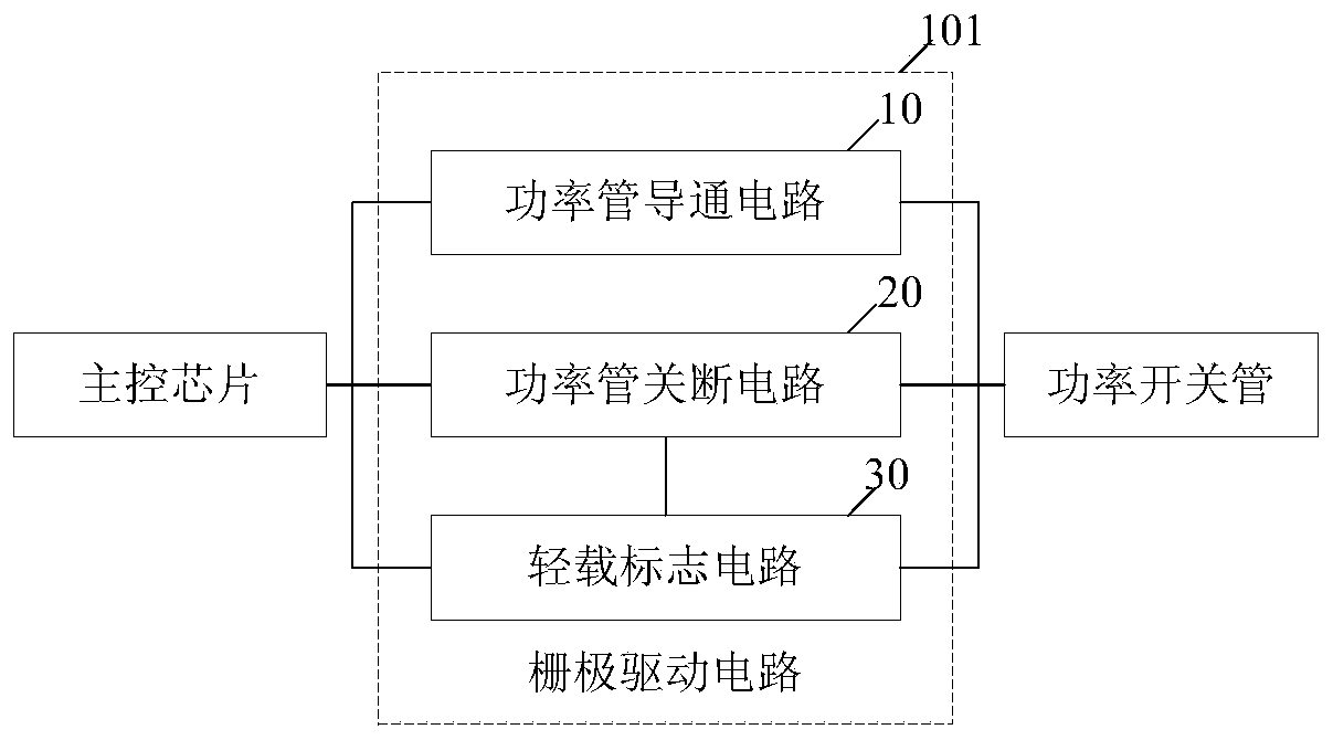
The invention belongs to the technical field of integrated circuits and discloses a gate driving circuit. The device comprises a power tube conduction circuit, a power tube turn-off circuit and at least one light load marking circuit; the input ends of the power tube conduction circuit, the power tube turn-off circuit and the light load marking circuits can be connected with a main control chip; the output ends of the power tube conduction circuit, the power tube turn-off circuit and the light load marking circuits can be connected with the grid driving end of a power switch tube; each light load marking circuit is connected with the power tube turn-off circuit; and each light load marking circuit generates a second power tube turn-off signal when the current working state of a switching power source circuit is a light load state, wherein the second power tube turn-off signal and first a power tube turn-off signal can jointly control the turn-off of the power switch tube. The inventionalso discloses a switching power source circuit. With the gate driving circuit provided by the invention adopted, full-load EMI and light-load standby power consumption can be well balanced.

Description

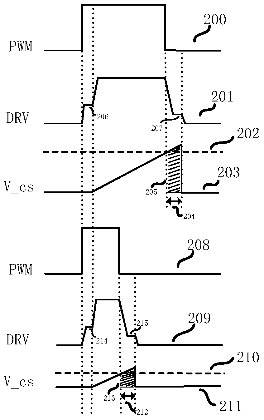
technical field [0001] The invention relates to the technical field of integrated circuits, in particular to a gate drive circuit and a switching power supply circuit comprising the gate drive circuit. Background technique [0002] In the switching power supply system, the control signal of the power switch tube is generated by properly converting the drive logic signal through the gate drive module, and finally drives the power tube to be turned on and off. When the isolated flyback converter is controlled by the primary side, energy is transferred between the primary coil and the secondary coil; the secondary coil transmits the output information to the auxiliary winding, and the transformer is used to realize the isolation of input and output. There are two processes of turning on and turning off the power tube in the general switching power supply control system. When the power tube is turned on, the primary inductor will form a path to the ground, and the input termina...

Claims


Application Information

Patent Timeline
IPC IPC(8): H02M1/08H02M3/335H02M1/44
CPCH02M1/08H02M1/44H02M3/33523H02M1/0054Y02B70/10
Inventor 虞楠楠朱勤为励晔黄飞明
Owner WUXI SI POWER MICRO ELECTRONICS
Why Eureka
Try Eureka