Control circuit and fly-back switching power supply system

A technology for control circuits and switching power supplies, applied in control/regulation systems, high-efficiency power electronic conversion, electrical components, etc., to solve problems such as lower overall efficiency, device damage, and low turn-on threshold voltage, to avoid accidental turn-on Effect

Active Publication Date: 2019-12-13
ON BRIGHT ELECTRONICS SHANGHAI
View PDF7 Cites 4 Cited by
  • Summary
  • Abstract
  • Description
  • Claims
  • Application Information

AI Technical Summary

Problems solved by technology

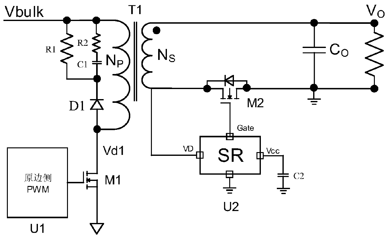
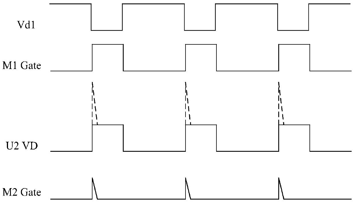
[0003] However, there is a parasitic capacitance C between the Gate-Drain (gate-drain) of the synchronous rectification Metal-Oxide-Semiconductor (MOS) transistor. gd , under the action of this parasitic capacitance, the voltage of the secondary side winding will be coupled at the Gate terminal of the synchronous rectification MOS tube to generate a peak voltage
[0004] Since the turn-on threshold voltage of the synchronous rectification MOS transistor is usually small, the peak voltage is usually higher than the turn-on threshold voltage of the synchronous rectification MOS transistor, so it may lead to false conduction of the synchronous rectification MOS transistor, which may lead to lower overall efficiency. , device damage, etc., bringing a series of safety issues

Method used


Image

  • Control circuit and fly-back switching power supply system
  • Control circuit and fly-back switching power supply system
  • Control circuit and fly-back switching power supply system

Examples


Embodiment Construction

[0022] The characteristics and exemplary embodiments of various aspects of the present invention will be described in detail below. In order to make the purpose, technical solutions and advantages of the present invention clearer, the present invention will be further described in detail below in conjunction with the accompanying drawings and specific embodiments. It should be understood that the specific embodiments described here are only configured to explain the present invention, not to limit the present invention. It will be apparent to one skilled in the art that the present invention may be practiced without some of these specific details. The following description of the embodiments is only to provide a better understanding of the present invention by showing examples of the present invention.

[0023] It should be noted that in this article, relational terms such as first and second are only used to distinguish one entity or operation from another entity or operation...


PUM


Abstract

The embodiment of the invention provides a control circuit and a fly-back switching power supply system. The control circuit is used for controlling the conduction of a synchronous rectification tubein the switching power supply system. The control circuit comprises a VD end which inputs the secondary winding voltage of the switching power supply system, a Gate end which is connected to the gateof the synchronous rectifier tube, and a charging current module, a diode, a first transistor, a capacitor and a second transistor which are connected between the VD end and the Gate end. One end of the charging current module is connected to the VD end, and the other end is connected to the anode of the diode. The cathode of the diode is connected to the drain of the first transistor, one end ofthe capacitor and the gate of the second transistor. The gate of the first transistor receives POR, and the source is grounded. The other end of the capacitor is grounded. The drain of the second transistor is connected to the Gate end, and the source is grounded. When the POR is at a low level, the second transistor is turned on. According to the technical scheme, the peak voltage of the Gate endcan be suppressed, and accidental conduction of the synchronous rectifier tube can be avoided.

Description

technical field [0001] The invention belongs to the field of integrated circuits, in particular to a control circuit and a flyback switching power supply system. Background technique [0002] With the continuous improvement of power efficiency standards, synchronous rectification control circuits have been more and more widely used in switching power supply systems. Compared with the traditional switching power supply system, the synchronous rectification control circuit can effectively increase the power density, improve the conversion efficiency, reduce the temperature rise, and also increase the complexity of the power system to a certain extent. Considering the cost of the entire power system, the synchronous rectification control circuit usually directly detects the secondary side winding voltage of the transformer to determine whether the synchronous rectification MOS transistor is turned on or not. [0003] However, there is a parasitic capacitance C between the Gate...

Claims


Application Information

Patent Timeline
Patent Type & Authority Applications(China)
IPC IPC(8): H02M1/32H02M3/335
CPCH02M1/32H02M3/33592Y02B70/10
Inventor 曹亚明方烈义
Owner ON BRIGHT ELECTRONICS SHANGHAI
Why Eureka
Try Eureka