
Optimized permanent magnet synchronous motor sensorless control method

A technology of permanent magnet synchronous motor and control method, which is applied in the direction of motor generator control, electronic commutation motor control, control system, etc., and can solve problems such as vibration generation and increased vibration

Inactive Publication Date: 2019-12-13
HUBEI UNIV OF ARTS & SCI
View PDF3 Cites 15 Cited by
  • Summary
  • Abstract
  • Description
  • Claims
  • Application Information

AI Technical Summary

Problems solved by technology

[0003] Among them, the sliding mode observer has the advantages of simple algorithm, good anti-interference ability, and fast response speed. Its disadvantage is that it will cause chattering due to inertia and measurement error interference, and at the same time, due to the application of low-pass filter, there will be a phase delay problem.
The current observation error in the observer changes dynamically, so a given fixed value sliding mode gain value may increase the jitter

Method used


Image

  • Optimized permanent magnet synchronous motor sensorless control method
  • Optimized permanent magnet synchronous motor sensorless control method
  • Optimized permanent magnet synchronous motor sensorless control method

Examples


Embodiment Construction

[0097] In order to facilitate those of ordinary skill in the art to understand and implement the present invention, the present invention will be described in further detail below in conjunction with the accompanying drawings and embodiments. It should be understood that the implementation examples described here are only used to illustrate and explain the present invention, and are not intended to limit this invention.

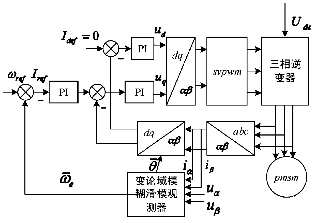
[0098] Such as figure 1 Shown is a schematic diagram of an optimized permanent magnet synchronous motor sensorless control system. It includes permanent magnet synchronous motor, three-phase inverter module, SVPWM module, vector control module, variable domain fuzzy sliding mode observer module. The control method adopts i d = 0 vector control, the three-phase current and voltage collected by the sensor is transformed into the current component i on the α-axis in the two-phase stationary coordinate system through Clark α , current component i on the β axis...


PUM


Abstract

The invention discloses an optimized permanent magnet synchronous motor sensorless control method, which comprises the following steps: Clark coordinate transformation is performed on a three-phase current and a three-phase voltage acquired by a sensor to obtain a voltage and a current under a two-phase static coordinate system, and the voltage under the two-phase static coordinate system is inputto a sliding mode current observer to obtain an observed current; the difference between the observed current and an actual current is input to a back electromotive force observer based on a saturation function to obtain an estimated initial value of back electromotive force, and the sliding mode gain ksmo in the back electromotive force observer based on a saturation function is adjusted by adopting a variable universe fuzzy control algorithm; the estimated initial value of back electromotive force is filtered through a variable cut-off frequency filter to obtain a smooth estimated value ofback electromotive force; and variable lag compensation design is performed on the rotor position after filtering, and the rotor speed and the rotor position value of the motor are calculated. The buffeting phenomenon can be weakened, the rotor speed and position information estimation precision can be improved, and good dynamic characteristic is achieved.

Description

technical field [0001] The invention relates to the field of permanent magnet synchronous motor control, in particular to a sensorless control method for optimizing a permanent magnet synchronous motor. Background technique [0002] In today's social production, permanent magnet synchronous motor has the characteristics of high torque ratio, convenient use and high power factor. It is used as the main power source output device, and its control performance research has been paid more and more attention. In the traditional permanent magnet synchronous motor control system, the motor rotor speed and position information are generally obtained by installing sensors, but the installation of sensors will reduce the space of the motor system, increase the production cost, and make the system more demanding on the operating environment. In order to eliminate the adverse effects of using sensors, the control algorithm in the position sensorless control technology is widely used to e...

Claims


Application Information

Patent Timeline
IPC IPC(8): H02P6/182H02P6/34H02P21/00H02P21/13H02P21/18H02P21/24
CPCH02P6/182H02P21/0007H02P21/001H02P21/13H02P6/34H02P21/18H02P21/24
Inventor 陈李济马强应保胜李华鑫伍娇高维士韩海风王硕张强
Owner HUBEI UNIV OF ARTS & SCI
Learn More