
Synchronization device for splicer, splicing processing system

A synchronization device and processing system technology, applied in the direction of electrical digital data processing, TV system components, data processing input/output process, etc., can solve screen tearing, cannot meet synchronization, and cannot realize multiple splicer output Synchronization and other issues to achieve a good expansion effect

Active Publication Date: 2021-12-14
BEIJING DIGIBIRD TECH CO LTD
View PDF11 Cites 0 Cited by
  • Summary
  • Abstract
  • Description
  • Claims
  • Application Information

AI Technical Summary

Problems solved by technology

However, the following requirements cannot be met:
[0004] (1) Unable to satisfy the synchronization between multiple input sources of a splicer
When multiple input source signals need to be spliced ​​into a higher resolution picture (such as 8k*4k, 16k*8k, etc.), during the long-term operation of multiple input source signals, due to differences in PCB routing, Factors such as clock skew cause the output to be out of sync and cause screen tearing
[0005] (2) Unable to fully synchronize one or more input sources of the splicer with the main playback device
In some scenarios, such as during 3D video transmission, it is necessary to keep the data sequence of each frame of the video strictly aligned with the main playback device, otherwise the video content will not be viewable
[0006] (3) It is impossible to achieve output synchronization between multiple splicers

Method used


Image

  • Synchronization device for splicer, splicing processing system
  • Synchronization device for splicer, splicing processing system
  • Synchronization device for splicer, splicing processing system

Examples


Embodiment Construction

[0047] Preferred embodiments of the present invention are described below with reference to the accompanying drawings. Those skilled in the art should understand that these embodiments are only used to explain the technical principle of the present invention, and are not intended to limit the protection scope of the present invention.

[0048] It should be noted that in the description of the present invention, the terms "first", "second", and "third" are only for convenience of description, rather than indicating or implying the relative importance of the devices, elements or parameters, Therefore, it should not be construed as limiting the invention.

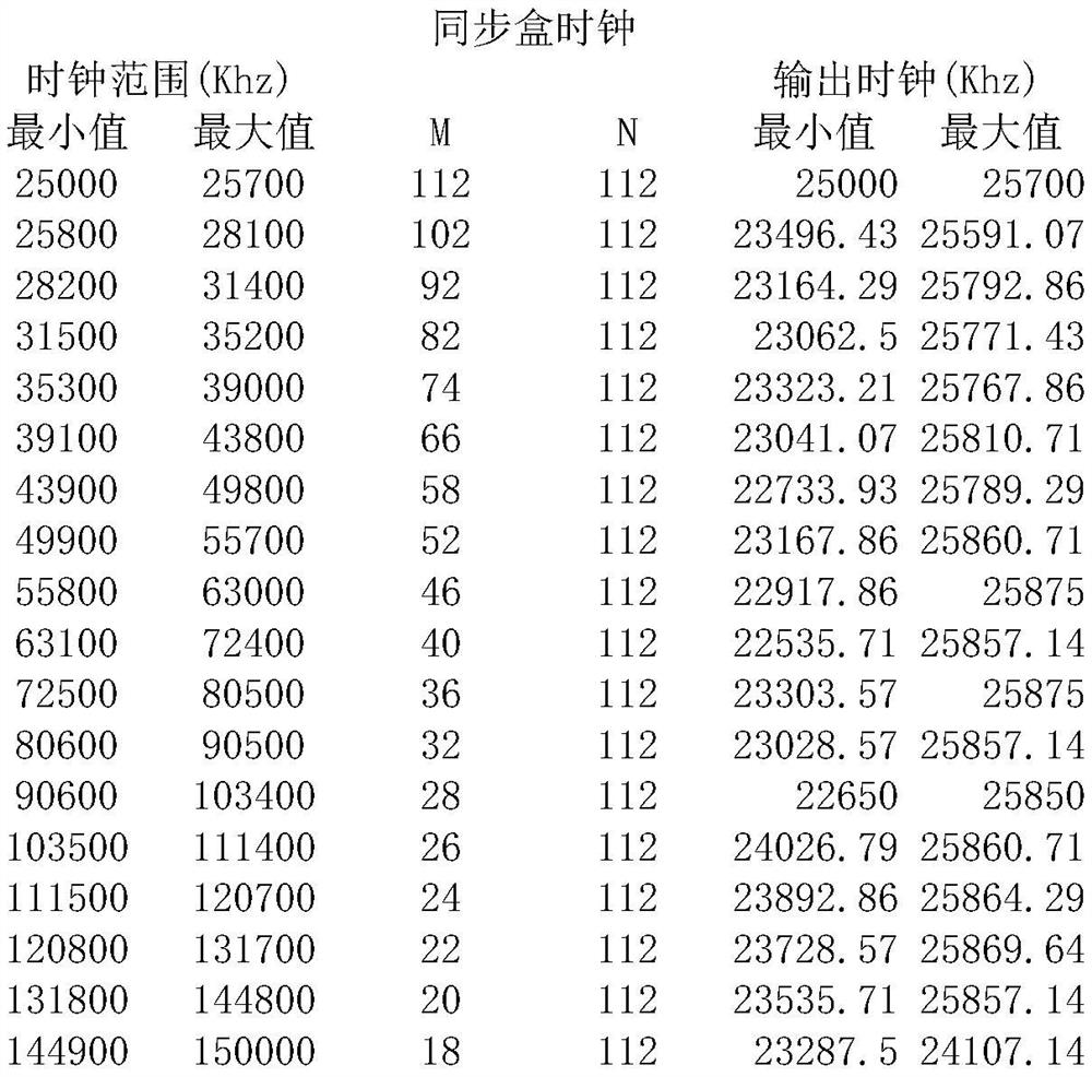
[0049] figure 1 It is a schematic diagram of the main components of the embodiment of the synchronization device for the splicer of the present invention. like figure 1 As shown, the synchronization device 100 of this embodiment includes: a video signal analysis module 110 , a control module 120 , a synchronization signal p...


PUM


Abstract

The invention relates to the technical field of splicers, in particular to a synchronization device and a splicing processing system for a splicer. The synchronization device of the present invention includes: a video signal analysis module, a control module, a synchronization signal processing module and a clock processing module. The video signal analysis module analyzes the video signal to obtain the first pixel clock and synchronous signal, divides the frequency of the first pixel clock by two to obtain the second pixel clock; the control module obtains the corresponding frequency multiplication value and division according to the second pixel clock frequency value; the clock processing module calculates the third pixel clock according to the second pixel clock, frequency multiplication value and frequency division value; the synchronization signal processing module uses the third pixel clock as a synchronization clock, and sends a synchronization instruction to one or more splicers so that the synchronizing device and the splicer can run synchronously; the invention solves the problem of synchronizing the input and output of the splicer when the video resolution changes and when there is an error in the refresh frequency, and realizes equipment expansion at the same time.

Description

technical field [0001] The invention relates to the technical field of splicers, in particular to a synchronization device and a splicing processing system for a splicer. Background technique [0002] The main function of the splicer is to divide a video signal into multiple display units, output the divided display unit signals to multiple display screens, and use multiple display screens to form a complete image. [0003] The video synchronization in the prior art is the synchronization between different output ports inside a splicer, which can realize the output synchronization between multiple output ports of an input source. However, the following requirements cannot be met: [0004] (1) Synchronization between multiple input sources of a splicer cannot be satisfied. When multiple input source signals need to be spliced ​​into a higher resolution picture (such as 8k*4k, 16k*8k, etc.), the multiple input source signals will be different due to differences in PCB routin...

Claims


Application Information

Patent Timeline
Patent Type & Authority Patents(China)
IPC IPC(8): H04N5/067H04N5/268G06F3/14
CPCH04N5/067H04N5/268G06F3/1446
Inventor 王洋董学明刘雨姚维久董志松王雅超李厚鹏
Owner BEIJING DIGIBIRD TECH CO LTD
Learn More