Automatic emptying device for fuel oil

An automatic emptying and emptying device technology, which is applied in the direction of fuel heat treatment device, combustion air/combustion-air treatment, charging system, etc., can solve the problems of uneven heating, low heating efficiency, and large space occupation, and achieve Save processing costs, improve heating efficiency, and save installation space

Active Publication Date: 2019-12-17
ZHEJIANG KEBODA IND
View PDF11 Cites 2 Cited by
  • Summary
  • Abstract
  • Description
  • Claims
  • Application Information

AI Technical Summary

Problems solved by technology

[0003] The existing automatic fuel emptying device includes a filter element assembly, a filter element assembly base, an electric fuel delivery pump assembly, a one-way valve assembly, and a water collection cup. On the base, it not only takes up a lot of space, but also needs to process the electric fuel pump assembly cavity, check valve assembly cavity, fuel discharge channel, bypass oil circuit, etc. on the filter element assembly base, and the processing cost is also high
In addition, the fuel does not necessarily pass through the heating area of ​​the water collection cup, and there is a possibility that part of the fuel is not heated, resulting in uneven heating, and the heated fuel is far away from the fuel discharge channel, and the fuel discharge channel is directly exposed to the external low temperature environment , the heat is directly lost to the external environment, there is a significant temperature drop, it is difficult to ensure the heating effect and the overall heating efficiency is low
[0004] In addition, the filter element assembly of the automatic fuel emptying device currently on the market is mostly a canister-type spin-on filter element. When replacing the filter element, it can only be replaced as a whole, resulting in unnecessary waste of various parts and resulting in increased maintenance costs for users. , and the canister-type spin-on filter element is designed in one piece, which produces a lot of waste, low resource utilization efficiency, and large environmental pollution

Method used


Image

  • Automatic emptying device for fuel oil
  • Automatic emptying device for fuel oil
  • Automatic emptying device for fuel oil

Examples


Embodiment Construction

[0026] The present invention will be described in detail below in conjunction with the accompanying drawings and specific embodiments.

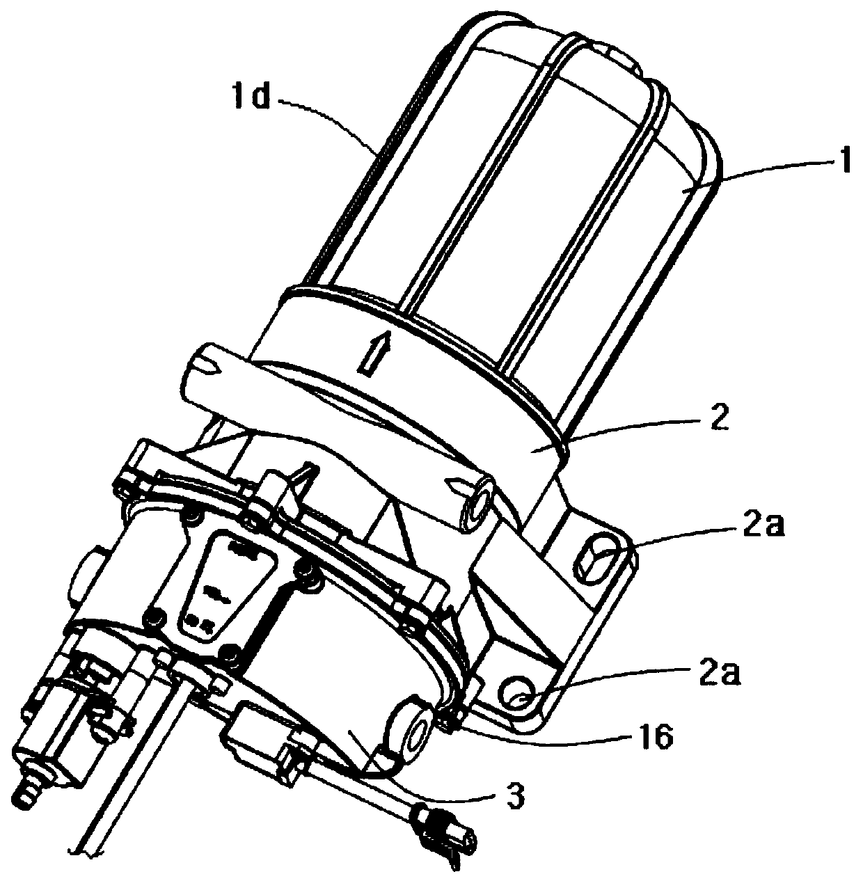
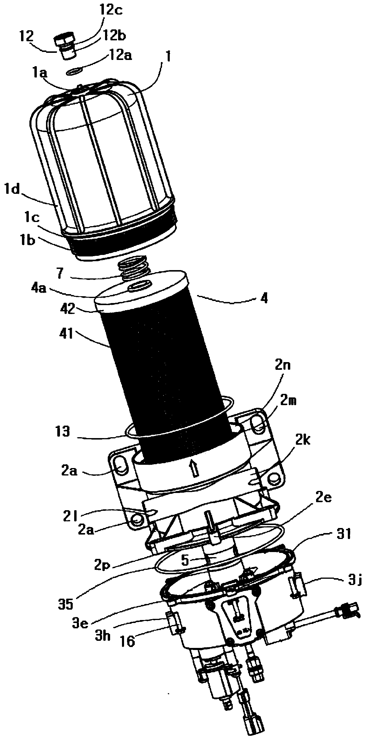
[0027] see Figure 1 to Figure 13 . An automatic fuel emptying device according to an embodiment of the present invention includes a housing 1 , a mounting bracket 2 , a water collecting cup 3 , a filter element assembly 4 , an electric fuel pump assembly 5 and two check valve assemblies 6 .

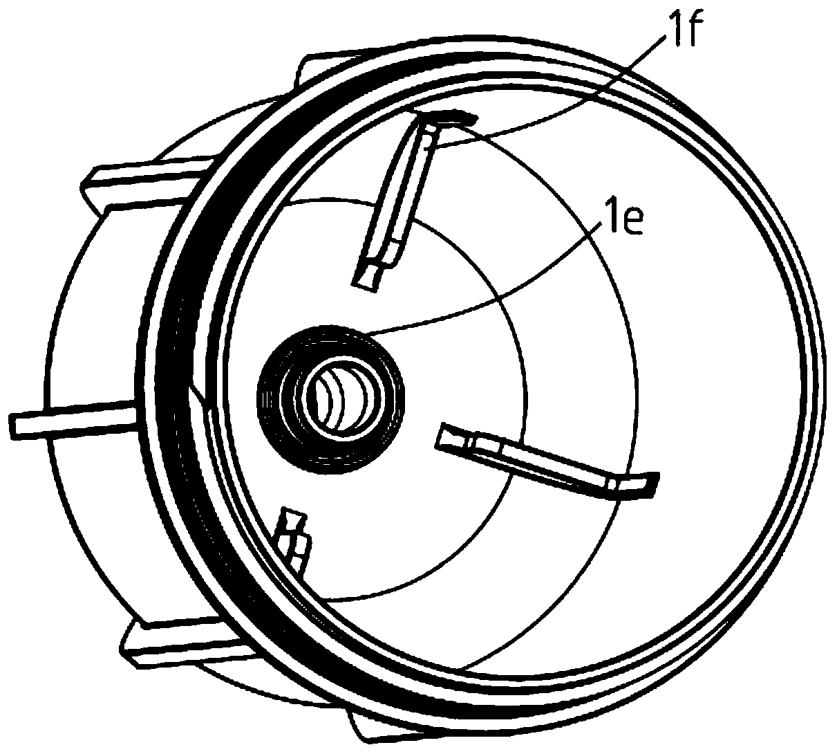
[0028] The lower end of the housing 1 is connected to the upper end of the installation bracket 2 , the lower end of the installation bracket 2 is connected to the upper end of the water collection cup 3 , and the housing 1 , the installation bracket 2 and the water collection cup 3 jointly define a chamber 9 . In this embodiment, to facilitate installation and maintenance, the lower end of the housing 1 is detachably connected to the upper end of the mounting bracket 2 , and the lower end of the mounting bracket 2 is detachably connected to the upper ...


PUM


Abstract

The invention discloses an automatic emptying device for fuel oil. The automatic emptying device for the fuel oil comprises a housing, an installation support, a water collection cup, a filter elementassembly, an electric oil delivery pump assembly and at least one check valve assembly. The housing, the installation support and the water collection cup define a chamber. The installation support is provided with an oil inlet port of the emptying device, and the water collection cup is provided with an oil outlet port of the emptying device and a heating device. The filter element assembly is arranged in the chamber, and provided with an inner cavity. The upper part of the electric oil delivery pump assembly is inserted into the inner cavity of the filter element assembly, and the lower endof the electric oil delivery pump assembly stretches into the inner cavity of the water collection cup. The electric oil delivery pump assembly comprises an electric oil delivery pump and an electricconnector; and the electric connector is provided with a fuel oil channel and bypass holes which are as many as the check valve assemblies. An air inlet port of the fuel channel communicates with anoil outlet port of the electric oil delivery pump, and an oil outlet port of the fuel channel communicates with the oil outlet port of the emptying device. The at least one check valve assembly is arranged in the at least one bypass hole separately in the manner of one-to-one correspondence. The automatic emptying device for the fuel oil is compact in structure, easy to machine and manufacture, and good in heating effect on the fuel oil in the water collection cup.

Description

technical field [0001] The invention relates to a fuel automatic emptying device. Background technique [0002] When the automobile fuel engine is started at low temperature and low speed, the low-pressure oil circuit often cannot automatically empty the air in the oil circuit, which causes the fuel engine to start unstable, difficult to start, or even unable to start, which affects the use of customers experience. Therefore, it is usually necessary to increase the automatic emptying device of automatic emptying and fast oil supply on the fuel engine. [0003] The existing automatic fuel emptying device includes a filter element assembly, a filter element assembly base, an electric fuel delivery pump assembly, a one-way valve assembly, and a water collection cup. On the base, it not only takes up a lot of space, but also needs to process the electric fuel pump assembly cavity, check valve assembly cavity, fuel discharge channel, bypass oil circuit, etc. on the filter eleme...

Claims


Application Information

Patent Timeline
Patent Type & Authority Applications(China)
IPC IPC(8): F02M37/54F02M37/44F02M37/34F02M37/28F02M37/48F02M37/42F02M37/08F02M31/02
CPCF02M31/02F02M37/08F02M37/28F02M37/34F02M37/42F02M37/44F02M37/48F02M37/54F02M37/36
Inventor 柯建豪庄才敖徐韬盛奇峰
Owner ZHEJIANG KEBODA IND
Why Eureka
Try Eureka