Radial plunger pump/motor and flow distribution structure thereof

A technology of plug pumps and motors, which is applied in the field of radial plug pumps/motors and their distribution structures. It can solve the problems of high design and processing requirements for distribution valves, delays in the opening and closing of distribution valves, and loss of volumetric efficiency, and improve friction and wear. and leakage problems, good sealing performance, and the effect of improving opening and closing hysteresis

Active Publication Date: 2019-12-17
ZHEJIANG UNIV
View PDF7 Cites 5 Cited by
  • Summary
  • Abstract
  • Description
  • Claims
  • Application Information

AI Technical Summary

Problems solved by technology

[0003] As an important working component of the hydraulic system, the working efficiency and life of the pump / motor directly affect the working performance and life of the entire hydraulic system. The commonly used flow distribution methods for pumps / motors are plate flow distribution or shaft flow distribution. The flow distribution pair structure adopts clearance fit, volumetric efficiency It is seriously affected, especially when it is applied to the pump / motor structure of high water-based hydraulic transmission system, the low viscosity of water will lead to a more serious loss of volumetric efficiency, and the requirements for the machining accuracy of the distribution pair are higher, and there is a problem of severe wear and low life
The valve distribution structure with better sealing performance is mainly used in the distribution of pumps. It has high requirements for the design and processing of the distribution valve. damage to the sealing surface

Method used


Image

  • Radial plunger pump/motor and flow distribution structure thereof
  • Radial plunger pump/motor and flow distribution structure thereof
  • Radial plunger pump/motor and flow distribution structure thereof

Examples


Embodiment Construction

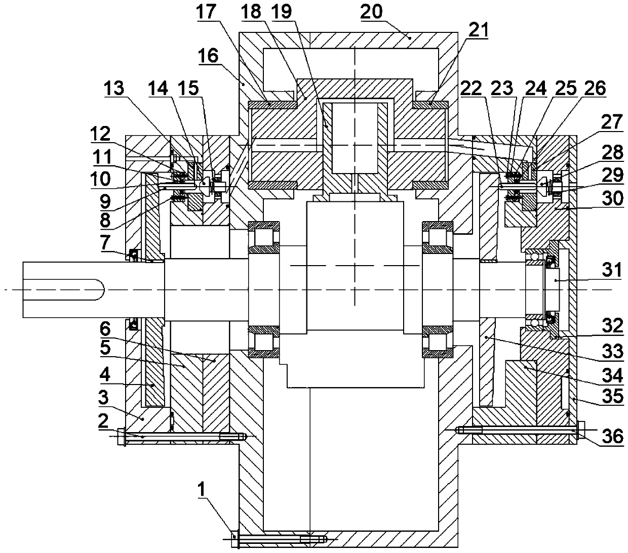
[0041] The present invention is described in further detail now in conjunction with accompanying drawing. These accompanying drawings are all simplified schematic diagrams, and only illustrate the basic structure of the present invention in a schematic manner, so only show the formation related to the present invention, and mainly carry out with the structure and working principle of this flow distribution structure applied to the swing cylinder type five-plunger motor Explanations, of course, are not limited to the specific structure of the swing-cylinder five-piston motor.

[0042] Such as figure 1As shown, the swing cylinder five-piston motor mainly includes a first end cover 3, a first pump / motor housing 16, a first swing cylinder sleeve 17, a swing cylinder 18, a plunger 19, a second pump / motor housing 20 , the second swing cylinder liner 21, the crankshaft 31, the second end cover 35; the plunger 19 is installed in the swing cylinder 18, and the two ends of the swing cy...


PUM


Abstract

The invention discloses a flow distribution structure of a radial plunger pump / motor. The flow distribution structure comprises a left flow distribution assembly and a right flow distribution assembly. The left flow distribution assembly comprises a first flow distribution disc, a first guide rod, a first fixing piece and a first one-way valve, wherein the first flow distribution disc is mounted on a rotary shaft of the radial plunger pump / motor, the first guide rod is slidably arranged on the first fixing piece, the first one-way valve is fixed to the first fixing piece, one end of the firstguide rod is in abut joint with a slope of the first flow distribution disc, and the other end of the first guide rod is in abut joint with a valve element of the first one-way valve; the right flow distribution assembly is similar to the left flow distribution assembly; and a mounting phase difference between the first flow distribution disc and a second flow distribution disc of the right flow distribution assembly is 180 degrees. The flow distribution structure is suitable for flow distribution of an oil-pressure / water-pressure pump / motor plunger, can effectively eliminate volume efficiencylosses caused by a flow distribution module of a flow distribution structure of a common disc, and can solve the problem of severe flow-distribution wear of the common disc; in addition, when the flow distribution structure is used for flow distribution of the pump, pressure losses caused during liquid suction / discharging of the pump can effectively reduced; and the flow distribution structure has the advantages of being simple in structure and low in cost.

Description

technical field [0001] The invention relates to the technical field of flow distribution of pumps / motors, in particular to a radial stop pump / motor and a flow distribution structure thereof. Background technique [0002] Hydraulic systems are widely used in various engineering fields. As people pay more and more attention to environmental protection, safety, health and other issues, higher requirements are put forward for the components in hydraulic systems, such as high efficiency, long life, and low leakage pollution. Wait. With the improvement of processing technology, more precise parts can be produced to reduce leakage, and the research and development of anti-wear materials and self-lubricating materials can improve the working life of hydraulic components. However, the structural problems, leakage and sealing problems of friction pairs in hydraulic components need to be solved urgently. [0003] As an important working component of the hydraulic system, the working e...

Claims


Application Information

Patent Timeline
Patent Type & Authority Applications(China)
IPC IPC(8): F04B53/10F03C1/047
CPCF03C1/0403F03C1/0435F03C1/0444F03C1/047F03C1/08F03C1/2423F04B1/0404F04B1/0448F04B1/0452F04B1/0465F04B1/0474F04B1/107F04B53/10F04B53/16
Inventor 郑克洪邱冰静王振宇李正
Owner ZHEJIANG UNIV
Why Eureka
Try Eureka