Supercharge Your Innovation With Domain-Expert AI Agents!

Rotating joint and oil cylinder hinge base integrated oil cylinder

A rotary joint, one-piece technology, applied in the field of oil cylinder hinge seat integrated oil cylinder and rotary joint, can solve the problems of difficulty in adjusting the unified height of multi-sector dam surfaces, slow dam surfaces, and inability to maintain a horizontal plane on the dam surface, and achieve extended maintenance. Cycle, the effect of increasing the service life

Pending Publication Date: 2019-12-17
湖南力威液压设备股份有限公司
View PDF0 Cites 1 Cited by
  • Summary
  • Abstract
  • Description
  • Claims
  • Application Information

AI Technical Summary

Problems solved by technology

Therefore, the prerequisite for flood discharge of the dam is to carry out when the hydraulic system is energized. In case of severe natural weather conditions such as heavy rain and lightning strikes, the hydraulic system is powered off or the hydraulic system fails, and the flood discharge of the dam will not be realized.
As a result, hydraulic lifting dams without support rods have appeared. However, in some rivers with normal water on both sides, when the dam gate is lowered, in order to overcome the buoyancy of the water on the back of the dam gate, the dam gate is lifted and lowered. When the hydraulic cylinder is used as a long-term support, although the hydraulic piping system does not leak oil outward, if an internal leak is formed between the piston of the double-acting hydraulic cylinder and the cylinder barrel, the rodless chamber passes through the hydraulic cylinder piston to the rod chamber. Oil flow, this kind of internal leakage is extremely unfavorable for long-term dam surface support, and the overall dam surface will slowly decline, resulting in the inability to maintain the horizontal level of the multi-fan dam surface, and it will become very difficult to adjust the uniform height of the multi-fan dam surface

Method used


Image

  • Rotating joint and oil cylinder hinge base integrated oil cylinder
  • Rotating joint and oil cylinder hinge base integrated oil cylinder

Examples


Embodiment 1

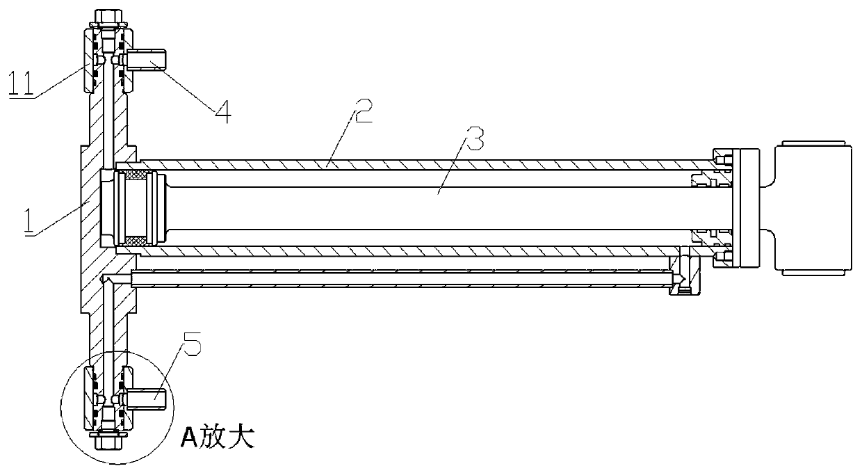
[0016] Embodiment 1, refer to Figure 1 to Figure 2 , the present invention includes an oil cylinder hinge seat integrated rotary joint 1, a cylinder body 2, a piston rod 3, a rodless chamber pipeline 4 and a rod chamber pipeline 5, and the piston rod 3 is set in the cylinder body 2, so that the cylinder body forms a The rod cavity and the rodless cavity, the rodless cavity pipeline 4 and the rod cavity pipeline 5 are installed on both ends of the rotary joint 1 of the oil cylinder hinge seat through the rotary joint sleeve 11, and respectively pass through the oil channel and the rodless cavity and the rod cavity. Cavities are connected, through the reversing valve in the hydraulic station, the oil inlet and outlet switching of the rodless cavity pipeline and the rod cavity pipeline is realized, so that the oil cylinder can be extended or retracted.

Embodiment 2

[0017] Embodiment 2, refer to Figure 1 to Figure 2 , the oil cylinder hinge seat integrated rotary joint 1 is provided with oil passages respectively connecting the rodless cavity pipeline 4 and the rodless cavity, and the rod cavity pipeline 5 and the stainless steel pipes coming out of the rod cavity. The rest are the same as any other embodiment of the present invention or the combination of more than two embodiments.

Embodiment 3

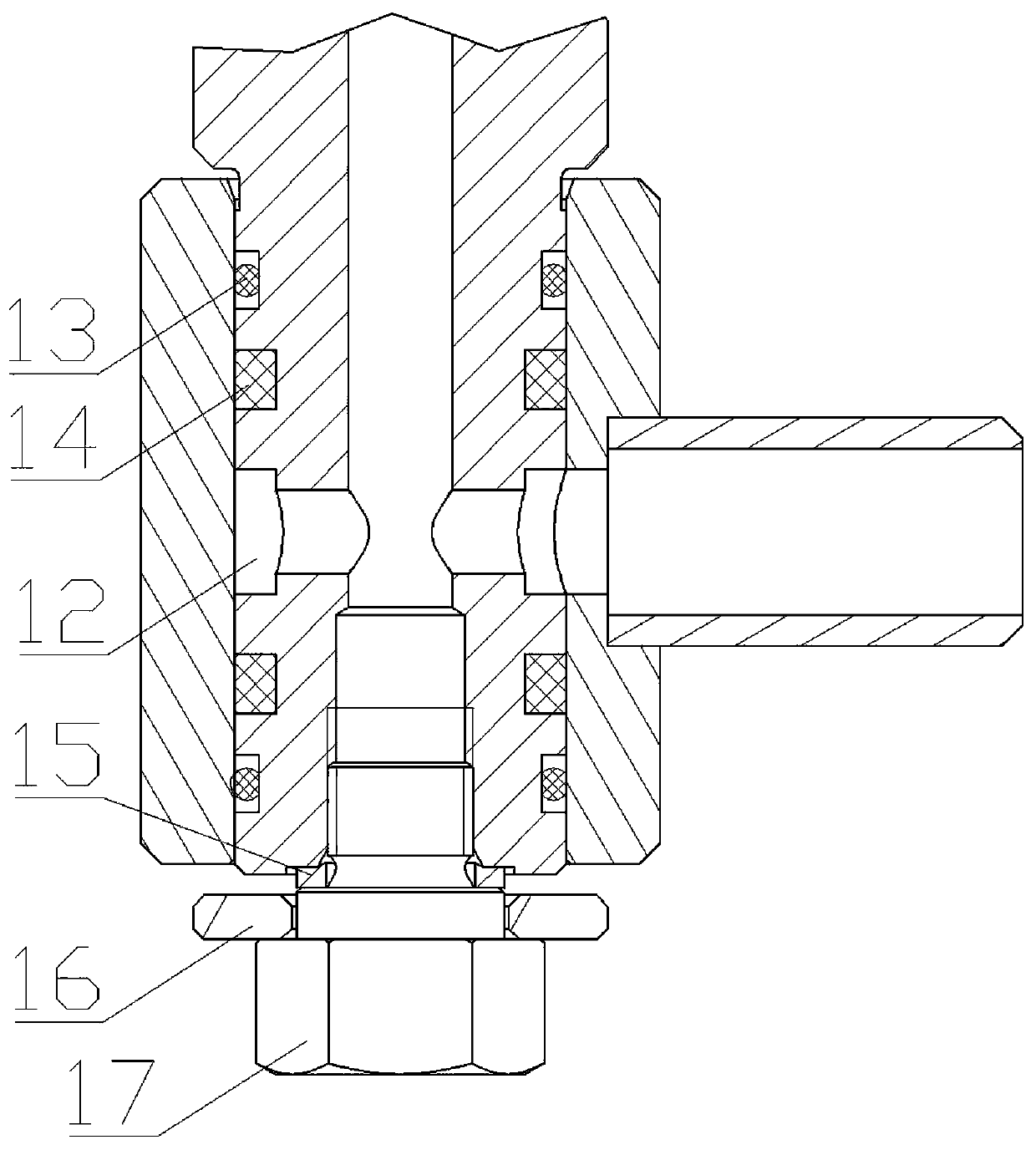
[0018] Embodiment 3, refer to Figure 1 to Figure 2 An annular gap 12 is provided in the integrated rotary joint 1 of the oil cylinder hinge seat, so that the oil channel in the integrated rotary joint 1 of the oil cylinder hinge seat is connected with the rotary joint sleeve 11, and the rotary joint sleeve 11 is connected with the rodless chamber pipeline 4 or There is a rod lumen pipeline 5 in communication. The rest are the same as any other embodiment of the present invention or the combination of more than two embodiments.


PUM


Abstract

The invention discloses a rotating joint and oil cylinder hinge base integrated oil cylinder, and mainly solves such technical problems as easy aging and damage of a high-pressure hose used for a hydraulic oil cylinder in a traditional barrage, low reliability and durability and inconvenient maintaining. The rotating joint and oil cylinder hinge base integrated oil cylinder is characterized by comprising an oil cylinder hinge base integrated rotating joint (1), a cylinder block (2), a piston rod (3), a rodless cavity pipeline (4) and a rod cavity pipeline (5); the piston rod (3) is sleeved with the cylinder block (2) to form a rod cavity and a rodless cavity in the cylinder block; and the rodless cavity pipeline (4) and the rod cavity pipeline (5) are mounted at the two ends of the oil cylinder hinge base integrated rotating joint (1) through rotating joint sleeves (11), and respectively communicate with the rodless cavity and the rod cavity through oil way channels. The rotating jointand oil cylinder hinge base integrated oil cylinder is mainly applied to the barrage.

Description

technical field [0001] The invention relates to an oil cylinder integrated with a rotary joint and an oil cylinder hinge seat. Background technique [0002] The hydraulic cylinder is used for lifting the dam door. Because the hydraulic cylinder moves with the door body, the A and B ports of the hydraulic cylinder can only be connected with high-pressure hoses. The high-pressure hoses are located at the bottom of the river bed, which has not been used for a long time. It is underwater and has silt, which is easy to age and damage. Once the high-pressure hose bursts, the door body supported by the oil cylinder will collapse in the form of gravity acceleration, causing a major safety hazard. Because the hydraulic lifting dam is located in the special operating environment inside the river bed, when the high-pressure hose needs to be replaced, it is necessary to retain a section of dry area, which makes the maintenance work extremely inconvenient. [0003] When the hydraulic li...

Claims


Application Information

Patent Timeline
Patent Type & Authority Applications(China)
IPC IPC(8): F15B15/14F16L39/06E02B7/36
CPCF15B15/149F15B15/1423F16L39/06E02B7/36
Inventor 张坚周骞
Owner 湖南力威液压设备股份有限公司
Features
  • R&D
  • Intellectual Property
  • Life Sciences
  • Materials
  • Tech Scout
  • Unparalleled Data Quality
  • Higher Quality Content
  • 60% Fewer Hallucinations
Learn More