
Kinematic viscosity measuring device and using method thereof

A kinematic viscosity and viscometer technology, applied in the measurement of DC flow characteristics, etc., can solve problems such as the inability to realize automatic measurement of a wide viscosity range, and achieve the effect of saving instrument cost, reasonable structure layout, and ensuring effectiveness.

Pending Publication Date: 2019-12-17
SHANGHAI INST OF MEASUREMENT & TESTING TECH
View PDF0 Cites 1 Cited by
  • Summary
  • Abstract
  • Description
  • Claims
  • Application Information

AI Technical Summary

Problems solved by technology

[0009] The invention provides a device for measuring kinematic viscosity, which is used to solve the problem that the existing device for measuring kinematic viscosity cannot automatically measure a wide viscosity range. The invention also provides a method for using the device for measuring kinematic viscosity, which is used to improve the measurement accuracy

Method used


Image

  • Kinematic viscosity measuring device and using method thereof
  • Kinematic viscosity measuring device and using method thereof
  • Kinematic viscosity measuring device and using method thereof

Examples


Embodiment Construction

[0046] Below in conjunction with accompanying drawing and specific embodiment the present invention is described in further detail:

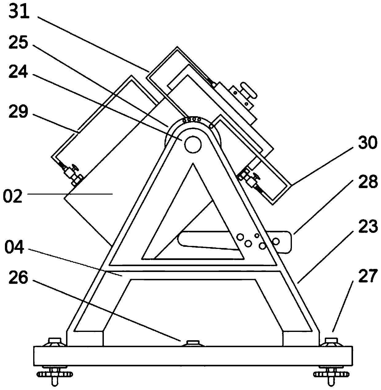
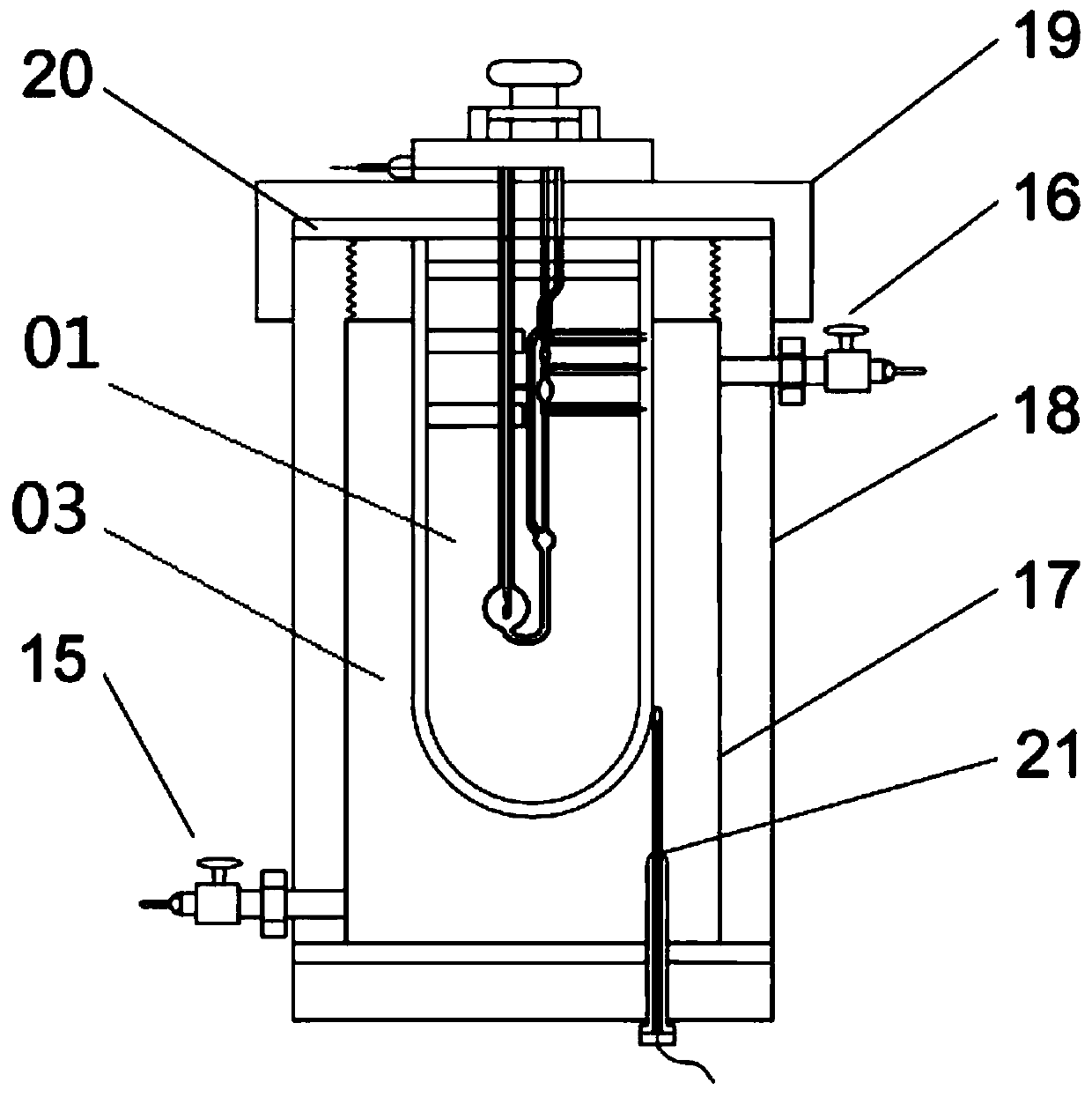
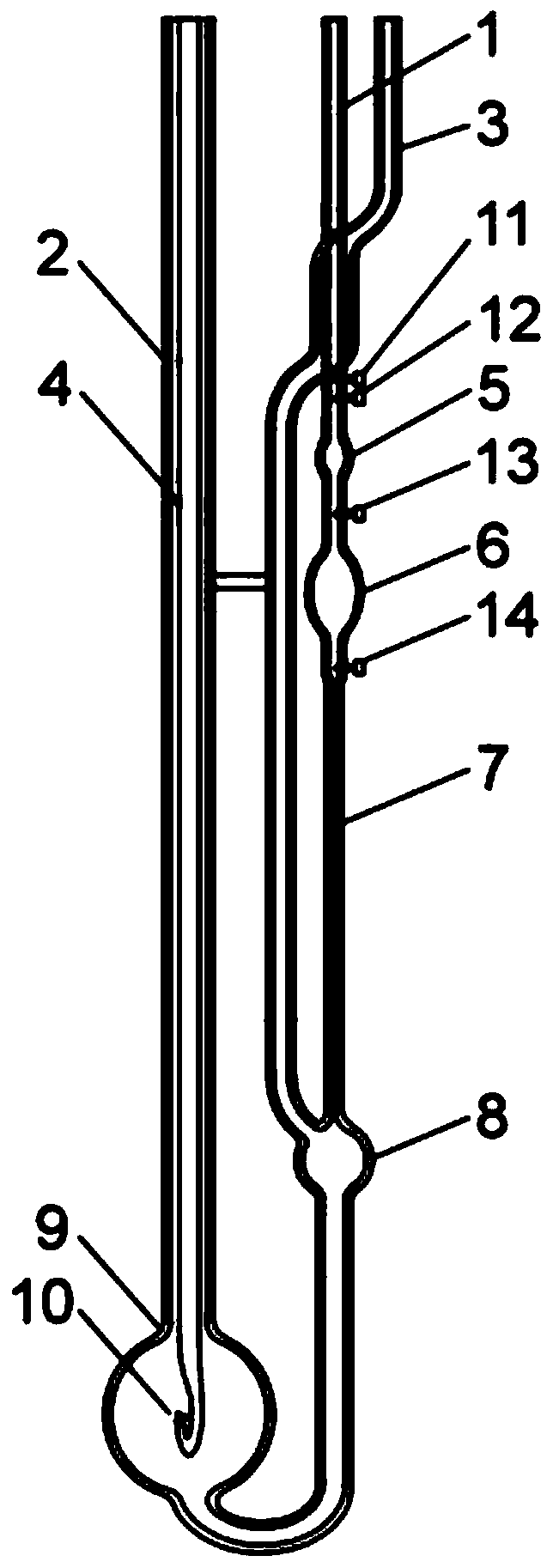
[0047] Such as figure 1 with figure 2 As shown, a device for measuring kinematic viscosity includes a double bulb capillary viscometer 01, a sealed thermostat 02, a fixed jacket 03, a positioning platform 04, an automatic timing system and a suction cleaning system; the sealed thermostat 02 is rotated and assembled on On the positioning platform 04; the double-bubble capillary viscometer 01 is fixed in the sealed thermostat 02 through the fixed jacket 03, and the main tube 1 and the upper opening of the branch pipe of the double-bulb capillary viscometer 01 are respectively connected to the suction cleaning system by pipes. The road is connected, and the double bulb capillary viscometer 01 adopts a different from the conventional double bulb timing structure. The double bulbs are the upper bulb 5 and the lower bulb 6 respectively. A liquid le...


PUM


Abstract

The invention relates to a kinematic viscosity measuring device, which comprises a double-bulb capillary viscometer, a sealed constant-temperature box, a fixing jacket, a positioning platform, an automatic timing system and a suction cleaning system, wherein the sealed constant-temperature box is rotationally assembled on the positioning platform, and the double-bulb capillary viscometer is fixedin the sealed constant-temperature box by means of the fixing jacket; openings in the upper ends of a main pipe and a branch pipe of the double-bulb capillary viscometer are communicated with the suction cleaning system by means of pipelines respectively, liquid level sensors are arranged on the upper and lower sides of an upper bulb and a lower bulb of the double-bulb capillary viscometer respectively, and the liquid level sensors are in data transmission connection with the automatic timing system respectively. Therefore, the problem that a kinematic viscosity measuring device in the prior art cannot realize automatic measurement in a wide viscosity range. The invention further provides a using method of the kinematic viscosity measuring device, and the using method is used for preciselymeasuring the viscosity-temperature properties of non-transparent liquids or liquids of various colors.

Description

technical field [0001] The invention relates to a device for measuring kinematic viscosity and a using method thereof. Background technique [0002] Viscosity measurement is an important means of controlling production process, ensuring production safety, evaluating product quality, medical testing and scientific research in the fields of petroleum, chemical industry, medicine, food, textile and national defense. Capillary viscometer is one of the important methods of kinematic viscosity measurement. It is recognized as the method with the highest accuracy in viscosity measurement and is indispensable in petroleum, chemical, pharmaceutical and other industries. [0003] The capillary viscometer is based on the principle of relative measurement, which is to measure the time required for a certain volume of liquid to flow through a capillary under the action of gravity. Common capillary viscometers are divided into positive flow Ping, Ubbelohde, and Finn capillary viscometers...

Claims


Application Information

Patent Timeline
IPC IPC(8): G01N11/04
CPCG01N11/04
Inventor 金愿朱绚华姜莹王灿刘波文慧卿陈超云
Owner SHANGHAI INST OF MEASUREMENT & TESTING TECH
Learn More