Electromagnetic riveting device for large-size thin-walled workpiece and riveting method

An electromagnetic riveting technology for thin-walled workpieces, which is applied in the field of electromagnetic riveting devices for large-scale thin-walled workpieces, can solve the problems of large recoil, low efficiency, and high processing costs, and achieve reduced volume and weight, reduced manufacturing costs, and reduced impact Effect

Pending Publication Date: 2019-12-20
哈工大机器人(岳阳)军民融合研究院
View PDF0 Cites 0 Cited by
  • Summary
  • Abstract
  • Description
  • Claims
  • Application Information

AI Technical Summary

Problems solved by technology

[0004] At present, the electromagnetic riveting equipment mainly used in the market has problems such as complex riveting equipment structure, low efficiency, high processing cost, unstable riveting quality, high labor intensity, applicable objects only for some workpieces with simple structure and large recoil force. The application is very limited

Method used


Image

  • Electromagnetic riveting device for large-size thin-walled workpiece and riveting method
  • Electromagnetic riveting device for large-size thin-walled workpiece and riveting method
  • Electromagnetic riveting device for large-size thin-walled workpiece and riveting method

Examples


Embodiment 1

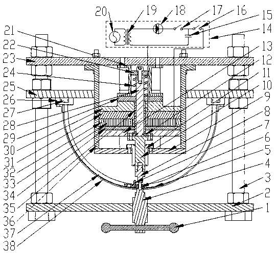
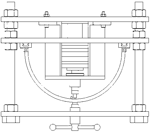
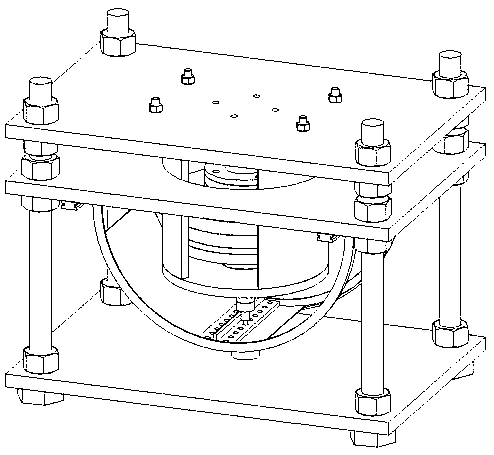
[0038] The invention provides an electromagnetic riveting device for large-scale thin-walled workpieces, such as Figure 1-3 As shown, it includes a screw handle 1, a base plate 2, a pillar screw 3, a screw rod 4, a punch 8, a linear bearing support plate 9, an amplifier 10, a linear bearing 11, a split insert 12, an amplifier partition 13, an electromagnetic Equipment 14, connecting seat 21, spring upper pressing block 22, upper plate 23, return spring 24, center guide rod 28, spring lower pressing block 29, coil carrier plate pressing block 30, coil carrier plate 31, coil insulating glue layer 32, Coil 33, driving plate 34, guide rod sleeve 35, steel sleeve 36 and bracket system 38, the coil insulating adhesive layer 32 is glued and coated on the outside of the coil 33, and the coil insulating adhesive layer 32 can be made of epoxy resin and polyamide The resin is mixed and prepared, and the coil 33 is wound on the coil carrier plate 31 .

[0039] Such as Figure 4 As shown,...


PUM


Abstract

The invention relates to an electromagnetic riveting device for a large-size thin-walled workpiece and a riveting method. Primary electromagnetic riveting equipment in the market at present has the problems that the riveting equipment is complex in structure, low in efficiency, high in processing cost, unstable in riveting quality, large in labor intensity, only suitable for some workpieces of simple structures, is great in recoil force and the like, and is limited greatly in practical engineering applications. The electromagnetic riveting device comprises a bottom plate. A group of strut screws are fixed to the bottom plate, a bracket system and an upper plate are mounted on the strut screws, the bottom of the upper plate is connected to a connecting seat, the connecting seat is arrangedon the outer side of an upper pressure block of a spring in a sleeving manner, the upper pressure block of the spring is fixedly mounted on a center guide bar, a reset spring is arranged between the upper pressure block of the spring and a lower pressure block of the spring, the reset spring is mounted on the outer side of the center guide bar in a sleeving manner, a guide bar bushing is arrangedon the outer side of the center guide bar in a sleeving manner, the guide bar bushing is connected to the lower pressure block of the spring, and the center guide bar is connected to a divided insertblock. The electromagnetic riveting device is used for electromagnetically riveting the large-size thin-walled workpiece.

Description

Technical field: [0001] The invention relates to an electromagnetic riveting device and riveting method for a large-size thin-walled workpiece. Background technique: [0002] With the growing call for energy saving and emission reduction, the manufacturing industry has more and more urgent requirements for lightweight, and the role of various lightweight materials in the industrial field is becoming more and more important. Traditional technologies challenged. [0003] Electromagnetic riveting provides a high-intensity pulse current to the discharge coil through a typical LRC discharge circuit, and then induces a mutually repelling eddy current magnetic field around the discharge coil and the driver piece. The electromagnetic riveting process does not produce any emissions during the production process. The whole process generates less heat, no waste gas, no sparks, no condensed water, no consumption of auxiliary materials, low carbon and environmental protection, low power...

Claims


Application Information

Patent Timeline
Patent Type & Authority Applications(China)
IPC IPC(8): B21J15/24B21J15/14
CPCB21J15/14B21J15/24
Inventor 罗通董东营王琼
Owner 哈工大机器人(岳阳)军民融合研究院
Why Eureka
Try Eureka