
3D printing method for metal combustion chamber of civil rocket engine

A rocket engine, 3D printing technology, applied in the field of 3D printing

Active Publication Date: 2019-12-20
NANJING ZHONGKE RAYCHAM TECH
View PDF16 Cites 3 Cited by
  • Summary
  • Abstract
  • Description
  • Claims
  • Application Information

AI Technical Summary

Problems solved by technology

[0003] The present invention aims to solve the technical problems of the metal combustion chambers of civil rocket engines in the prior art, and proposes to provide a 3D printing method for the metal combustion chambers of civil rocket engines. The mechanical structure has been topologically optimized into a grid shape and meets the requirements of metal 3D printing

Method used


Image

  • 3D printing method for metal combustion chamber of civil rocket engine

Examples


Embodiment Construction

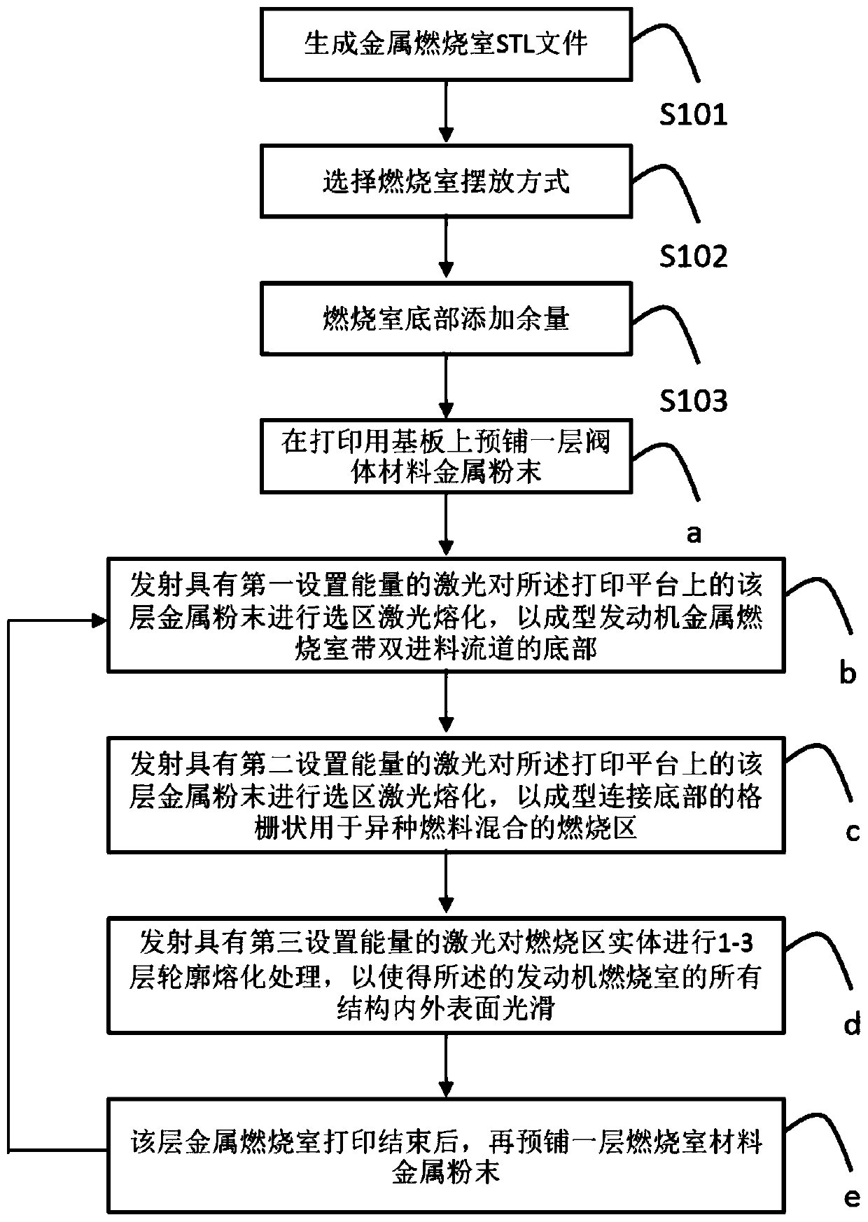
[0025] In order to better understand the technical content of the present invention, specific embodiments are given together with the attached drawings for description as follows.

[0026] Aspects of the invention are described in this disclosure with reference to the accompanying drawings, which show a number of illustrated embodiments. Embodiments of the present disclosure are not necessarily intended to include all aspects of the invention. It should be understood that the various concepts and embodiments described above, as well as those concepts and embodiments described in more detail below, can be implemented in any of a number of ways, which should be the concepts and embodiments disclosed by the present invention and not Not limited to any implementation. In addition, some aspects of the present disclosure may be used alone or in any suitable combination with other aspects of the present disclosure.

[0027] Such as figure 1 as shown, figure 1 It is a schematic fl...


PUM


Abstract

The invention provides a 3D printing method for a metal combustion chamber of a civil rocket engine. The 3D printing method includes the steps that a, the placement manner of the combustion chamber and the adding margin of the bottom of the combustion chamber are determined, then operation is conducted according to a printing program of a metal combustion chamber part STL file, and a layer of metal powder of an engine combustion chamber material is pre-laid on a base plate used for printing; b, a laser with first set energy is transmitted so that the bottom, with double feeding runners, of themetal combustion chamber of the engine can be formed; c, a laser with second set energy is transmitted, and forming connection of a bottom grid shape is achieved; d, a laser with third set energy istransmitted so that the inner and outer surfaces of all the structures of the combustion chamber of the engine can be smooth; and e, after smelting of a preference zone of the previous layer of metalpowder is over, powder with the same thickness is laid continuously, and operation is conducted continuously according to the sequence till the operation is completed according to the printing programof a metal combustion chamber part STL file. By means of the 3D printing method, the rocket engine combustion chamber better facilitating heterogeneous fuel mixed combustion can be manufactured, andthe inner and outer surfaces of the structures are smooth.

Description

technical field [0001] The invention relates to the technical field of 3D printing, in particular to a 3D printing method for a civil rocket engine metal combustion chamber Background technique [0002] The combustion chamber of a civil rocket engine is one of the important parts of a rocket engine. The combustion chamber provides a storage and combustion place for the propellant charge. At present, the design of the mechanical structure of the rocket engine combustion chamber is limited by traditional manufacturing methods, so that different fuels cannot be fully mixed and burned and have to carry more fuel, which increases the cost of civilian rockets and reduces economic benefits. the field of application. Contents of the invention [0003] The present invention aims to solve the technical problems of the metal combustion chambers of civil rocket engines in the prior art, and proposes to provide a 3D printing method for the metal combustion chambers of civil rocket eng...

Claims


Application Information

Patent Timeline
IPC IPC(8): B22F3/105F02K9/62F02K9/34B33Y10/00
CPCF02K9/62F02K9/34B33Y10/00B22F10/00B22F12/17B22F10/28B22F10/36B22F10/366B22F10/32Y02P10/25
Inventor 李俊仪申赛刚邢月华
Owner NANJING ZHONGKE RAYCHAM TECH
Learn More