
Thin-wall high-position-precision hole system component machining method

A part processing and high position technology, which is applied in the determination and adjustment of multiple factors and parameters, can solve the problems of excessive precision and size, low production qualification, etc., and achieve the effect of improving stability and good product quality.

Active Publication Date: 2019-12-20
GUIZHOU YONGHONG AVIATION MACHINERY
View PDF7 Cites 2 Cited by
  • Summary
  • Abstract
  • Description
  • Claims
  • Application Information

AI Technical Summary

Problems solved by technology

[0004] The technical problem to be solved by the present invention is to provide a thin-walled high-position precision hole for the problems of excessive position accuracy and size that are easy to occur in the processing of parts pointed out in the background technology, and the production qualification is extremely low (the pass rate is less than 10%). Parts processing method

Method used

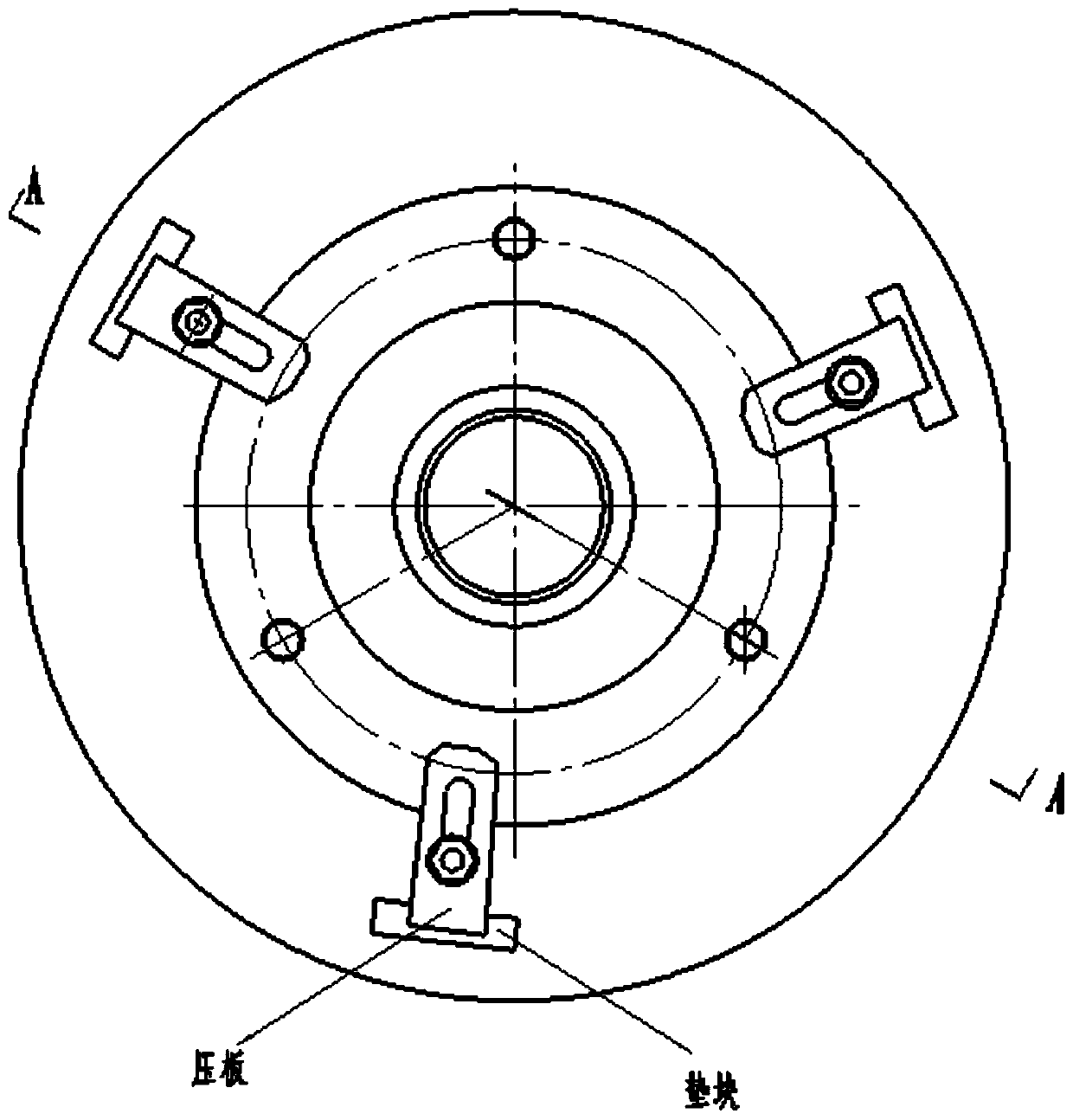

Image

  • Thin-wall high-position-precision hole system component machining method
  • Thin-wall high-position-precision hole system component machining method
  • Thin-wall high-position-precision hole system component machining method

Examples


Embodiment Construction

[0045]The present invention will be further described below in conjunction with accompanying drawing and specific embodiment, but should not be interpreted as that the scope of the subject matter of the present invention is only limited to following embodiment, under the situation of not departing from above-mentioned technical thought of the present invention, all according to this field Various modifications, substitutions and alterations made by ordinary technical knowledge and common means are included in the scope of the present invention.

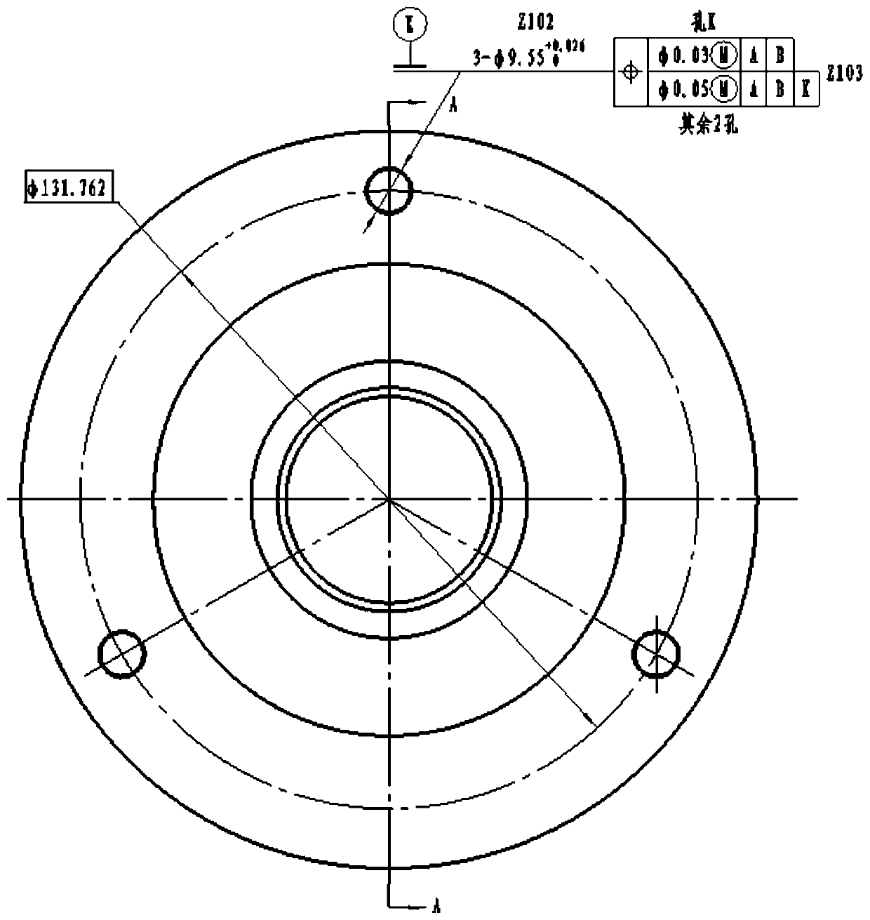
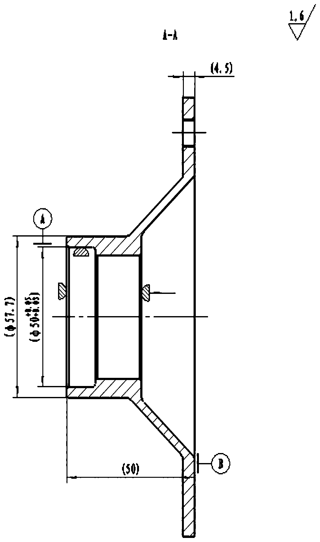
[0046] This embodiment is processing parts as attached figure 1 with figure 2 As shown, in an aerospace field, thin-walled, ultra-thin-walled hole system parts with high positional accuracy requirements, the specific technology should refer to the attached figure 1 with figure 2 , using the technological method described in the present invention can accurately position and process.

[0047] 1. Difficulty analysis: According to th...


PUM

PropertyMeasurementUnit
Roughnessaaaaaaaaaa

Abstract

The invention discloses a thin-wall high-position-precision hole system component machining method. Through cutting tool selection and clamping, equipment pre-running, a machining reference, machine tool precision checking, cutting amount distribution, cutting force control, component clamping and other multi-aspect technical adjustment, combination and optimization, guaranteeing of high-position-precision machining elements of components and process upgrading are achieved, and effective control over the high-position precision of the components is achieved.

Description

technical field [0001] The invention relates to a processing method of thin-walled and ultra-thin-walled hole system parts requiring high position accuracy in the field of aerospace, in particular to a method for determining and adjusting multiple factors and parameters that affect final processing accuracy. Background technique [0002] Such as figure 1 with figure 2 As shown, it is an aviation high-speed core component. In this component, the connecting flange parts made of titanium alloy require extremely high shape and position tolerances for the dimensions related to the hole system. During the first and many years of product manufacturing, conventional processing methods cannot guarantee the design requirements, and the pass rate is less than 10%. And the processing pass rate is extremely unstable, that is: in addition to the extremely high position accuracy of this series of parts and the difficult-to-cut processing characteristics of titanium alloy materials; the ...

Claims


Application Information

Patent Timeline
IPC IPC(8): B23P13/02
CPCB23P13/02
Inventor 吕仕强龙召木杨玉超
Owner GUIZHOU YONGHONG AVIATION MACHINERY
Learn More