
Channel steel machining, corner shearing and bending machine and machining method

A technology of bending machine and channel steel, applied in metal processing equipment, shearing device, shearing machine equipment and other directions, can solve the problems of channel steel deformation, low quality channel steel, lack of support at the shear angle, etc., to prevent deformation, The effect of improving channel steel quality and reducing machining defect rate

Active Publication Date: 2019-12-20
杭州百尊五金制造有限公司
View PDF9 Cites 3 Cited by
  • Summary
  • Abstract
  • Description
  • Claims
  • Application Information

AI Technical Summary

Problems solved by technology

[0006] The present invention can solve the problem that the existing channel steel bending machine usually adopts the method of rotating rollers to bend the channel steel at a certain angle. This method makes the bending place have radians, and the bending of the channel steel that requires a right angle angle cannot be completed. , and can solve the problem that the existing channel steel bending machine lacks support for the shear angle during use, which easily leads to deformation in the process of channel steel processing, resulting in lower quality of processed channel steel and high processing defect rate.

Method used


Image

  • Channel steel machining, corner shearing and bending machine and machining method
  • Channel steel machining, corner shearing and bending machine and machining method
  • Channel steel machining, corner shearing and bending machine and machining method

Examples


Embodiment Construction

[0033] The embodiments of the present invention will be described in detail below with reference to the accompanying drawings, but the present invention can be implemented in many different ways defined and covered by the claims.

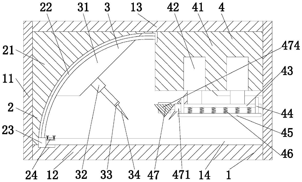
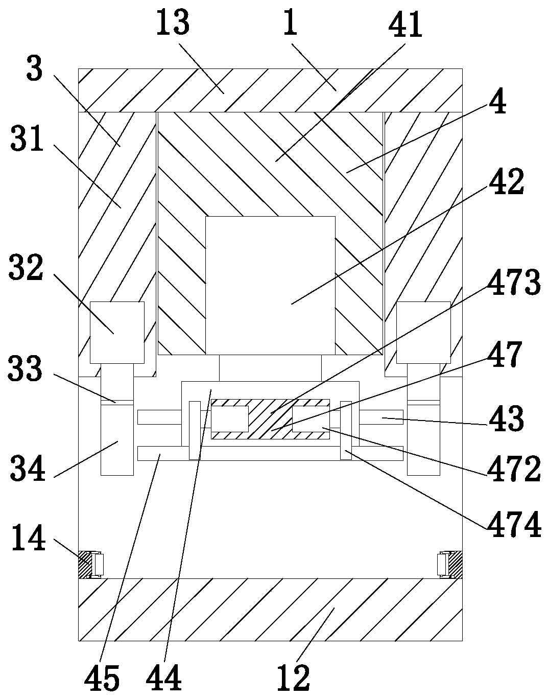
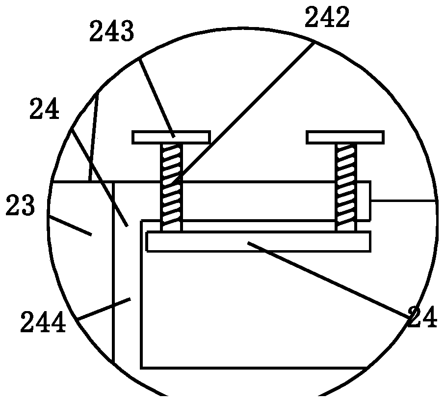
[0034] Such as Figure 1 to Figure 4 Shown is a channel-steel angle shearing bending machine, including a support device 1, a bending device 2, a shear angle device 3 and a fixing device 4. A bending device 2 is installed on the end surface, a fixing device 4 is installed on the inner end surface on the right side of the support device 1 , and an angle shearing device 3 is installed symmetrically on the front and back of the support device 1 .

[0035] The support device 1 includes a support plate 11, a bottom plate 12, a top plate 13 and a limit mechanism 14. The support plate 11 is installed on the end faces of both sides of the bottom plate 12, and the top plate 13 is installed between the upper sides of the support plate 11, and the bottom plate...


PUM


Abstract

The invention relates to a channel steel machining, corner shearing and bending machine and a machining method. The machine comprises a supporting device, a bending device, corner shearing devices anda fixing device. The cross section of the supporting device is of a homocentric-squares-shaped structure, the bending device is mounted on the inner end face of the left side of the supporting device, the fixing device is mounted on the inner end face of the right side of the supporting device, and the corner shearing devices are symmetrically installed on the front and back of the supporting device. The machine can solve the problems that an existing channel steel bending machine often adopts a roller cooperation mode to make channel steel bent by a certain angle, accordingly bent portions have radians, and bending of channel steel needing right angles cannot be completed. Besides, the problems that in the using process of the existing channel steel bending machine, corner shearing portions are lack of supporting, the channel steel is likely to deform in the machining process, the quality of the machined channel steel is low, and the defective rate of machining is high can be solved.

Description

technical field [0001] The invention relates to the field of steel processing equipment, in particular to a shear angle bending machine for channel steel processing and a processing method. Background technique [0002] Channel steel is a long strip of steel with a groove-shaped cross-section. It belongs to carbon structural steel for construction and machinery. It is a section steel with a complex cross-section. Channel steel is mainly used in building structures, curtain wall engineering, mechanical equipment and vehicle manufacturing. [0003] A bending machine is a device that bends profiles such as plates, round steel, square steel, and steel pipes at a certain angle. The bending machine in the prior art cannot bend channel steel. If a mold is used for bending, different bending angles According to the requirements, different molds must be made, and the production cost is relatively high. [0004] At present, for the existing channel steel bending machine, there are t...

Claims


Application Information

Patent Timeline
Patent Type & Authority Applications(China)
IPC IPC(8): B23P23/04B21D7/06B21D7/16B23D15/04B23D33/02
CPCB21D7/06B21D7/16B23D15/002B23D15/04B23D33/02B23P23/04
Inventor 莫小雨张康乐
Owner 杭州百尊五金制造有限公司
Learn More