
A compound film glazing heat energy recovery unit

A light-heat and unit technology, which is applied in the direction of printing machines, lighting and heating equipment, and general parts of printing machinery, can solve the problems of energy waste, unfavorable energy saving and consumption reduction of enterprises, and inability to reduce cost expenditures, so as to reduce costs and prevent The effect of heat dissipation and convenient operation

Active Publication Date: 2020-12-01
ANHUI THE PARKSON SOURCE PACKAGING MATERIALS
View PDF20 Cites 0 Cited by
  • Summary
  • Abstract
  • Description
  • Claims
  • Application Information

AI Technical Summary

Problems solved by technology

[0003] The plastic sheet also needs to be polished during the processing process. The plastic sheet needs to be heated during glazing, which will generate a lot of heat, and then the plastic sheet needs to be cooled. If the high heat is discharged directly, it will cause energy consumption. waste, which is not conducive to energy saving and consumption reduction of enterprises, and cannot reduce cost expenditure

Method used

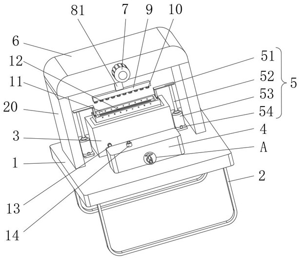
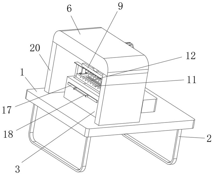
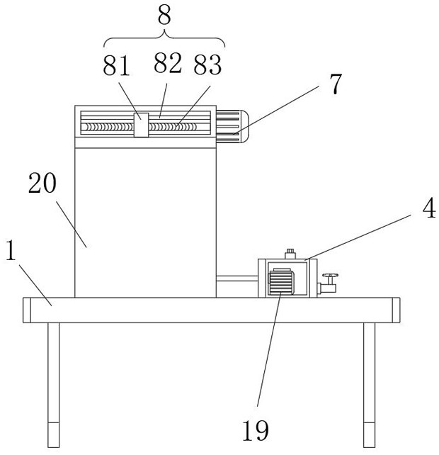

Image

  • A compound film glazing heat energy recovery unit
  • A compound film glazing heat energy recovery unit
  • A compound film glazing heat energy recovery unit

Examples


Embodiment 1

[0028] Such as Figure 1-6 As shown, the embodiment of the present invention provides a light and heat energy recovery unit for laminating coating, including a support plate 1, and two symmetrically arranged support legs 2 are fixedly connected to the lower side wall of the support plate 1. The support legs 2 are U-shaped, and the support legs 2 Hollowing treatment, and the support leg 2 is made of stainless steel die-casting, the surface of the support leg 2 is treated by coating the nano-varnish anti-oxidation film coating process, the upper side wall of the support plate 1 is fixedly connected with two vertical plates 20 arranged symmetrically at the front and rear , and the upper end of the riser 20 is fixedly connected with the top plate 6, the interior of the top plate 6 is provided with a moving cavity, the side wall of the top plate 6 is fixedly connected with the motor 7, the output end of the motor 7 penetrates into the interior of the top plate 6 and is connected wit...

Embodiment 2

[0033] The difference between the second embodiment and the first embodiment is that the motor 7, the threaded rod 83, and the threaded bar 81 are changed into electric telescopic rods, and the electric telescopic rods are connected with the placement frame 11, so that the movement in the horizontal direction can also be realized, and the automatic upward movement can be realized. light work.


PUM


Abstract

The invention provides a composite film varnishing heat energy recovery unit, and relates to the technical field of composite film printers. The composite film varnishing heat energy recovery unit comprises a worktable; two vertical plates symmetrically arranged front and back are fixedly connected to the upper side wall of the worktable; a top plate is fixedly connected between the two vertical plates, and is connected with a lifting module; the lower end of the lifting module is connected with a moving plate; a coiled heating pipe is arranged on the lower side wall of the moving plate; a belt conveyor is arranged on the upper side wall of the worktable, and is positioned between the two vertical plates; cavities are formed in the vertical plates; chutes are formed in one side walls of the cavities; and two guide modules are symmetrically arranged between the two vertical plates. Through the guide modules, a guide effect on box bodies is achieved by guide wheels, and the box bodies move between two rows of the guide wheels, so that the deviation problem of the box bodies on the belt conveyor is effectively prevented, and the falling from the belt conveyor is prevented.

Description

technical field [0001] The invention relates to the technical field of lamination printing machines, in particular to a lamination coating heat energy recovery unit. Background technique [0002] Glazing is to coat a layer of colorless transparent paint on the surface of the printed matter, which can protect and increase the gloss of the printed matter after drying. Glazing can not only enhance the surface brightness, but also protect the printed graphics. Therefore, it is widely used in packaging boxes, books, The surface processing of albums, posters and other printed matter, the glazing process of printed matter mainly includes: solvent-based coating glazing, solvent-free UV glazing, etc. Due to the unique advantages of UV glazing technology itself, it has been developed in the development of post-press processing. With obvious advantages, it is widely used in the finishing and processing of surface printed matter. [0003] The plastic sheet also needs to be polished dur...

Claims


Application Information

Patent Timeline
Patent Type & Authority Patents(China)
IPC IPC(8): B41F23/08F25D1/02
CPCB41F23/08F25D1/02Y02P70/10
Inventor 刘文峰黄怡晴刘家岐
Owner ANHUI THE PARKSON SOURCE PACKAGING MATERIALS
Learn More