A steel structure channel steel connecting member

A technology for connecting components and steel structures, used in building structures, buildings, etc., can solve the problems of small application scope, troublesome disassembly of steel structure profiles, and profile damage, etc. Effect

Inactive Publication Date: 2020-09-01
安徽天筑杭萧钢构股份有限公司
View PDF7 Cites 0 Cited by
  • Summary
  • Abstract
  • Description
  • Claims
  • Application Information

AI Technical Summary

Problems solved by technology

[0003] However, the following difficult problems exist in the current channel steel when connecting. One, the traditional channel steel needs to be welded at the joint when connecting, and the smoke generated during welding affects the health of the staff, and it is troublesome to dismantle the steel structure profiles after welding; 2. When the traditional channel steel is connected by thread, the profile will be greatly damaged, which will greatly reduce the mechanical properties of the profile at the channel steel joint, which will affect the subsequent use of the channel steel, and the joint will also become a danger to the entire channel steel. point, which increases the risk factor of the support frame spliced ​​by channel steel; 3. The traditional channel steel connection mechanism can only be connected to one type of channel steel structure, and the scope of application is small and the utilization rate is low

Method used


Image

  • A steel structure channel steel connecting member
  • A steel structure channel steel connecting member
  • A steel structure channel steel connecting member

Examples


Embodiment Construction

[0030] The embodiments of the present invention will be described in detail below with reference to the accompanying drawings, but the present invention can be implemented in many different ways defined and covered by the claims.

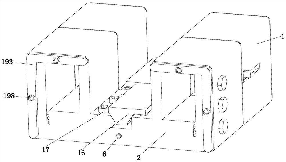
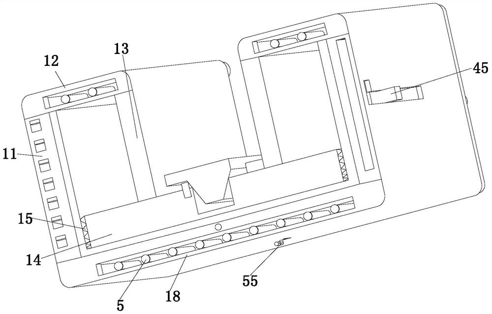
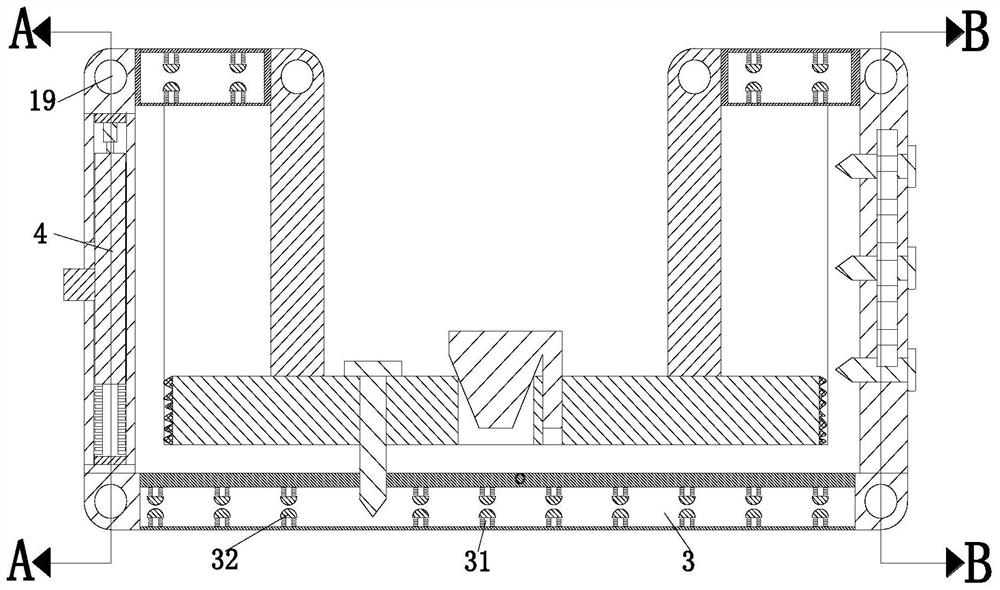
[0031] like Figure 1 to Figure 7 As shown, a steel structure channel steel connecting member includes a No. 1 butt joint device 1 and a No. 2 butt joint device 2. The No. 1 butt joint device 1 and No. 2 butt joint device 2 are connected by a retaining threaded straight rod 6. A push rod mechanism 5 is installed on the front side of the lower end of the docking device 1, and a clamping mechanism 3 is installed on the rear side of the lower end of the No. 2 docking device 2. The No. 1 docking device 1 and the No. 2 docking device 2 have the same structure.

[0032] The No. 1 docking device 1 includes a straight plate 11, a connecting plate 12, a rotating plate 13, a pressing plate 14, a rubber pad 15, a fastening nail 16, a locking nut 17 and a base ...


PUM


Abstract

The invention relates to a steel structure profile connecting member. The connecting member comprises a No.1 butt jointing device and a No.2 butt jointing device which are connected through retainingthreaded straight bars, a push rod mechanism is mounted on the front side of the lower end of the No.1 butt jointing device, a clamping mechanism is mounted on the back side of the lower end of the No.2 butt jointing device, and the structures of the No.1 butt jointing device and the No.2 butt jointing device are the same. The jointing member can solve the following problems during connection of existing steel channels: 1, welding is required at connection positions during connection of traditional steel channels, smoke produced during welding affects physical health of workers, and steel structure profiles after welding are troublesome to dismount; and 2, traditional steel channels can greatly damage profiles during threaded connection, so that mechanical performance of profiles in connection positions of steel channels is substantially reduced, follow-up use of the steel channels is affected, connection positions can become dangerous points of whole steel channels, so that the dangercoefficient of a support frame spliced by steel channels is increased.

Description

technical field [0001] The invention relates to the technical field of steel member connection, in particular to a channel steel connection member of a steel structure. Background technique [0002] Channel steel is a long strip of steel with a groove-shaped cross-section. It belongs to carbon structural steel for construction and machinery. It is a section steel with a complex cross-section. Channel steel is mainly used in building structures, curtain wall engineering, mechanical equipment and vehicle manufacturing. In today's building structures, channel steel has gradually been widely used due to its advantages of less material consumption, energy saving and environmental protection, good seismic performance, light weight, and convenient construction. , Smaller channel steels are combined and spliced ​​to form a larger steel structure profile support frame, and this larger steel structure profile support frame is used to support other structures. [0003] However, the f...

Claims


Application Information

Patent Timeline
Patent Type & Authority Patents(China)
IPC IPC(8): E04B1/24E04B1/58
CPCE04B1/2403E04B1/5818E04B2001/2406
Inventor 何淑敏李晨
Owner 安徽天筑杭萧钢构股份有限公司
Why Eureka
Try Eureka