
Integrated oil tank isolation valve

An isolation valve and integrated technology, applied in valve details, safety valves, balance valves, etc., can solve problems such as large load, the opening sensitivity of the air supply valve assembly cannot meet the use requirements, and affect the safety and life of the fuel tank. , to achieve the effect of ensuring safety, reducing pressure difference and improving sensitivity

Pending Publication Date: 2019-12-20
STANT AUTOMOTIVE SYST SUZHOU
View PDF1 Cites 2 Cited by
  • Summary
  • Abstract
  • Description
  • Claims
  • Application Information

AI Technical Summary

Problems solved by technology

However, in the actual operation process, when the electromagnetic valve assembly is dragged to displace the air supply valve assembly in the axial direction, due to the negative pressure, its own load is relatively large, so that the opening sensitivity of the air supply valve assembly cannot be reached. Meet the requirements of use, thus affecting the safety and life of the fuel tank

Method used


Image

  • Integrated oil tank isolation valve
  • Integrated oil tank isolation valve
  • Integrated oil tank isolation valve

Examples


Embodiment Construction

[0029] In the description of the present invention, it should be understood that the orientation or positional relationship indicated by the terms "upper", "lower", "left", "right", etc. is based on the orientation or positional relationship shown in the drawings, and is only for It is convenient to describe the present invention and simplify the description, instead of indicating or implying that the device or element referred to must have a specific orientation, be constructed and operated in a specific orientation, and therefore cannot be understood as a limitation to the present invention.

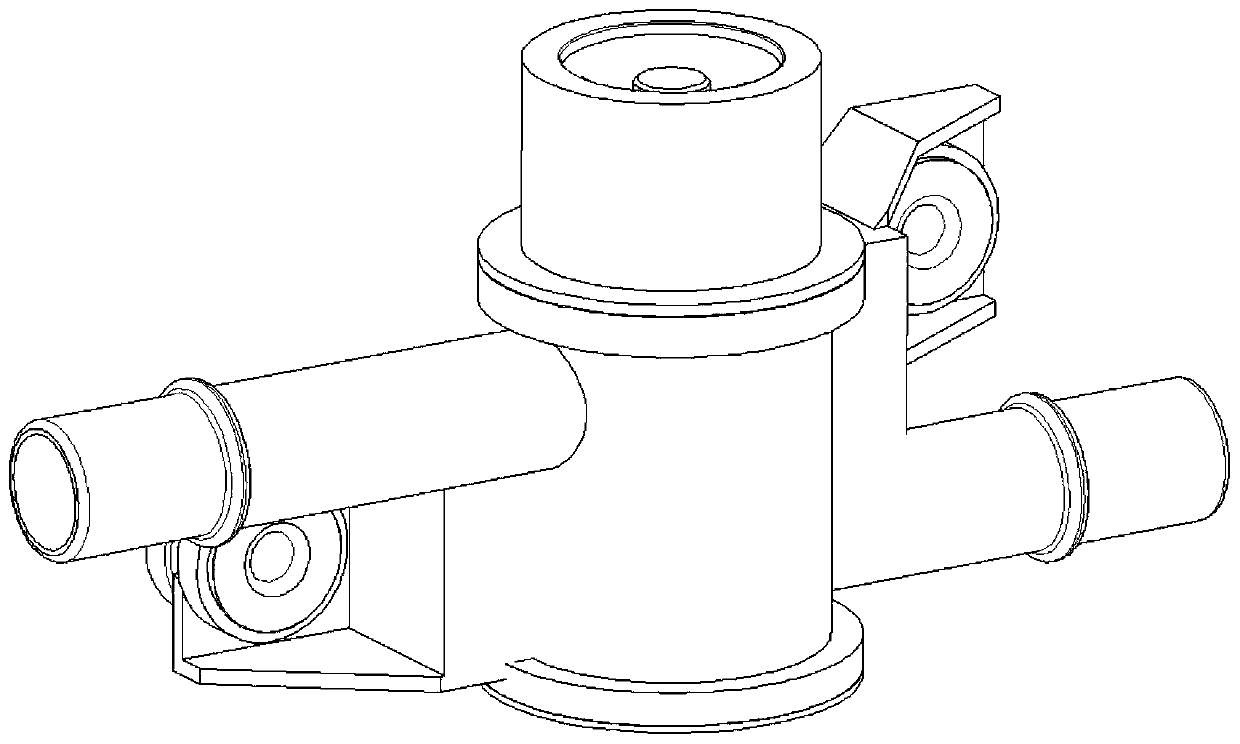
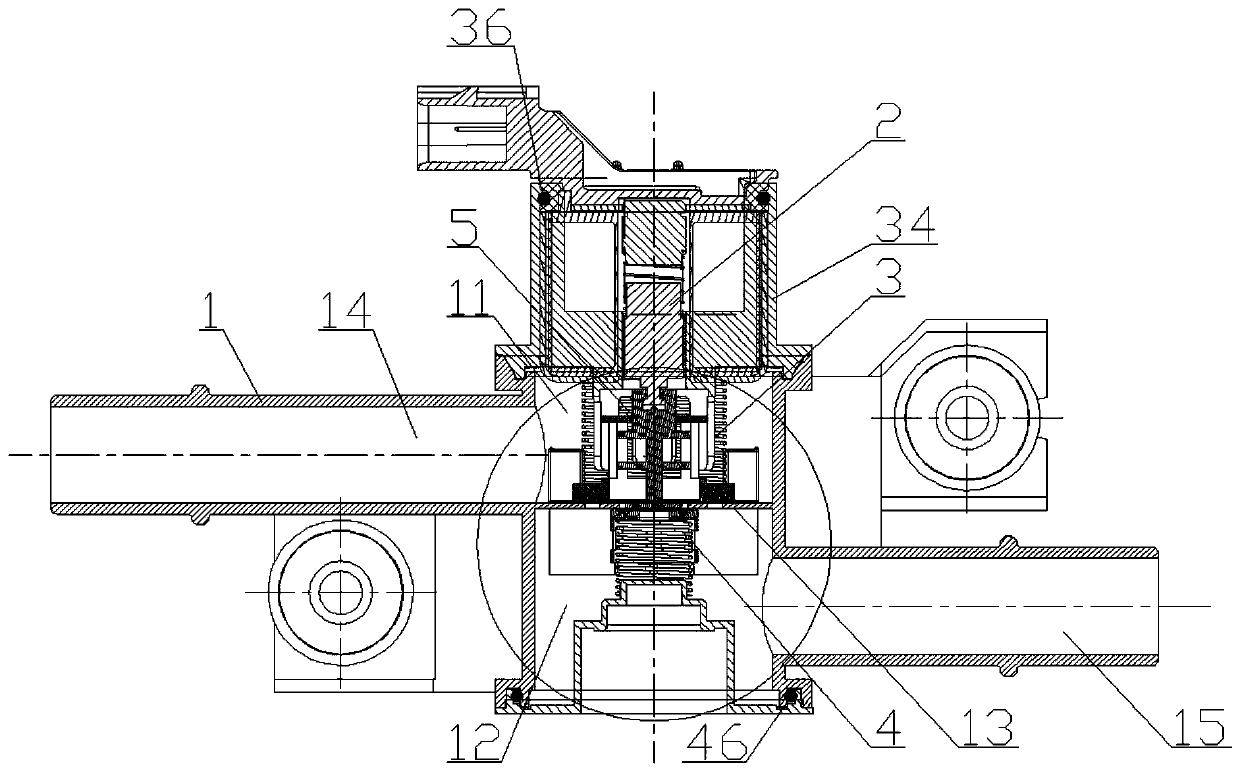
[0030] The content of the present invention will be further described in detail below in conjunction with specific embodiments. figure 2 , image 3 The three-dimensional schematic diagram and the cross-sectional view of the integrated fuel tank isolation valve in the present invention are respectively shown. It can be seen that it is mainly composed of the housing 1, the solenoid valve ass...


PUM


Abstract

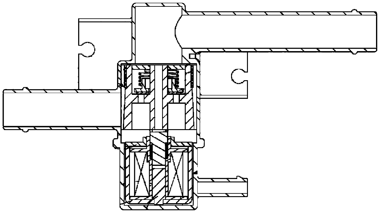
The invention relates to an integrated oil tank isolation valve. The integrated oil tank isolation valve comprises a shell body, an electromagnetic valve assembly, an air supply valve assembly, a deflation valve assembly and a sealing terminal. A first cavity body and a second cavity body are arranged in the shell body, the shell body is provided with a partition plate for partition. A first channel and a second channel are respectively extended along the first cavity body and the second cavity body. A central through hole and a circumferential through hole are formed in the partition plate. The air supply valve assembly is used for blocking the circumferential through hole and is arranged in the first cavity body, and the air supply valve assembly is provided with an air supply cavity connected with the first channel. The deflation valve assembly is arranged in the second cavity body, and the deflation valve assembly is provided with a deflation cavity connected with the second channel. The sealing terminal is arranged in the air supply cavity and can penetrate through the central through hole, and the sealing terminal is driven by the electromagnetic valve assembly to move to determine partition or communication of the air supply cavity and the deflation cavity. At the initial stage when the electromagnetic valve assembly is energized, the sealing terminal is subjected to small-distance displacement to relieve the partition of the deflation valve assembly, that is, the pressure difference between the air supply cavity and the deflation cavity is reduced when the air supply valve assembly is opened.

Description

Technical field [0001] The invention relates to the technical field of automobile manufacturing, in particular to an integrated fuel tank isolation valve. Background technique [0002] In the prior art, in the gasoline vapor discharge system, gasoline vapor generated in the fuel tank is discharged to the carbon canister through the exhaust valve, and is effectively adsorbed by the activated carbon inside. After the engine is started, fresh air is drawn into the carbon canister, and the fuel vapor absorbed by the activated carbon in the carbon canister is brought back into the engine for combustion to improve fuel efficiency. However, in plug-in hybrid models, there is a long-term use of electric drive mode. In this mode, the canister has no desorption function, which can easily cause the adsorption capacity of the canister to reach saturation. After that, the fuel vapor will be directly discharged into the atmosphere, resulting in Environmental pollution and fuel waste. In addi...

Claims


Application Information

Patent Timeline
IPC IPC(8): F16K17/00F16K31/06B60K15/035F02M25/08
CPCF16K17/00F16K31/06B60K15/03519F02M25/0836F02M2025/0845
Inventor 孙红明周彪刘鹏
Owner STANT AUTOMOTIVE SYST SUZHOU
Learn More