
Condensation device for rapidly cooling high-temperature smoke
A technology of condensing device and high-temperature flue gas, applied in steam/steam condensers, lighting and heating equipment, etc., can solve problems such as high-temperature flue gas cooling, and achieve the effect of rapid cleaning, reducing volume and increasing process flow
- Summary
- Abstract
- Description
- Claims
- Application Information
AI Technical Summary
Problems solved by technology
Method used
Image

Examples
Embodiment Construction
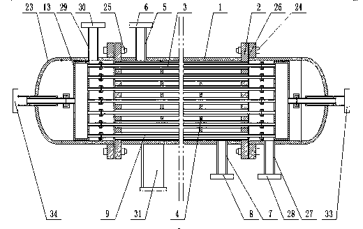
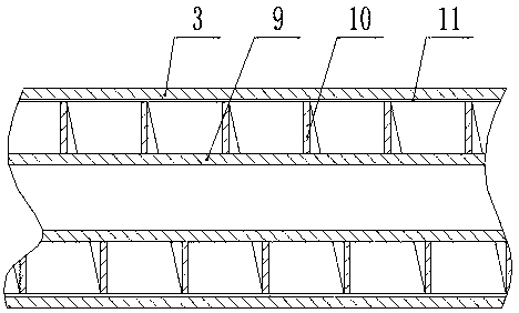
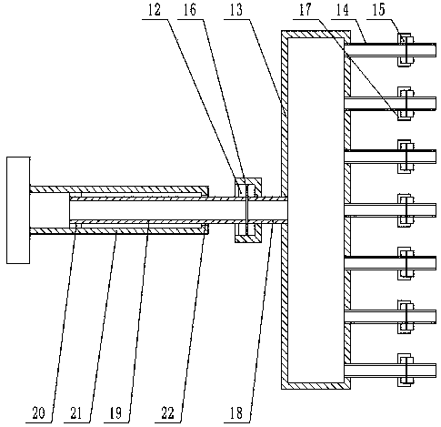
[0025] The present invention is specifically described below in conjunction with accompanying drawing, as Figure 1-4 As shown, in this implementation:
[0026] The invention of this application lies in the structural design of the double water-cooled condensing device, combined with the attached figure 1 And attached figure 2 , the double water-cooled condensing device includes a fixed tube plate 2 installed at both ends of the tank body 1, a number of heat dissipation smoke tubes 3 are installed between the two fixed tube plates 2, and the heat dissipation smoke tubes 3 are evenly distributed on the fixed tube plate 2, and the tank body 1 A number of partitions 4 are installed inside, and the partitions 4 cross and distribute on both sides of the tank body 1. The partitions 4 are fixedly connected with the heat dissipation smoke pipe 3, and the upper end of the tank body 1 is equipped with a water outlet pipe 5, and a water discharge method is installed on the outlet pipe ...
PUM
 Abstract
Description
Claims
Application Information