Efficient heat exchanger device

A technology of heat exchangers and shell-and-tube heat exchangers, which is applied in the field of high-efficiency heat exchanger devices, can solve problems such as adhering impurities and affecting heat transfer effects, and achieve high-efficiency heat transfer, improve heat transfer effects, and improve heat transfer efficiency. The effect of thermal efficiency

Active Publication Date: 2019-12-20
陈庆高
View PDF10 Cites 21 Cited by
  • Summary
  • Abstract
  • Description
  • Claims
  • Application Information

AI Technical Summary

Problems solved by technology

[0005] The purpose of the present invention is to solve the above-mentioned problems, and to design a high-efficiency heat exchanger device, which has the function of high-efficiency heat exchange, and solves the problem of sticking on the tube wall inside the heat exchanger after a long time of work in the existing heat exchanger. For the problem of impurity attached to the heat exchange effect, the rotation of the rotating shaft is driven by the flow of the high-temperature heat-conducting medium, so that the spiral scraper on the rotating shaft can clean the inner wall of the heat exchange tube, so that the inside of the heat exchange tube is kept clean and effectively guaranteed Improve the heat exchange effect of the heat exchanger when it works for a long time, and make the heat exchange efficiency of the heat exchanger more efficient

Method used


Image

  • Efficient heat exchanger device
  • Efficient heat exchanger device
  • Efficient heat exchanger device

Examples


Embodiment Construction

[0024] The present invention is specifically described below in conjunction with accompanying drawing, as Figure 1-4 As shown, in this implementation:

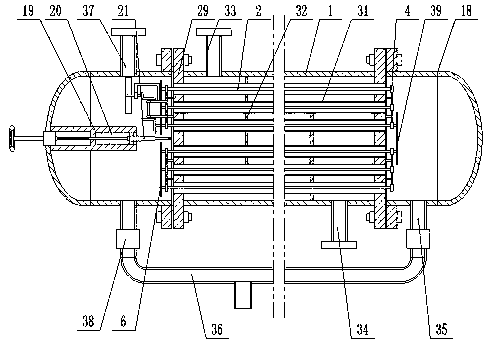
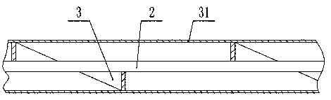
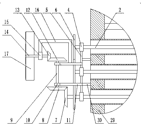
[0025] The invention of this application lies in the structural design of the hydraulic heat exchange tube cleaning device, combined with the attached figure 1 , attached figure 2 And attached image 3 , the hydraulic heat exchange tube cleaning device includes a number of rotating shafts 2, spiral scrapers 3 are installed on the rotating shaft 2, rotating bearings 4 are installed at both ends of the rotating shaft 2, and between the adjacent rotating bearings 4 on each group of rotating shafts 2 Connected by the connecting rod 5, one end of the rotating shaft 2 is equipped with a rotating gear 6, and the rotating gears 6 on two adjacent rotating shafts 2 are engaged with each other, and one end of one of the rotating shafts 2 is equipped with a transmission bevel gear 7, the transmission bevel gear The transmission bevel...


PUM


Abstract

The invention discloses an efficient heat exchanger device. The efficient heat exchanger device comprises a tank body, wherein a tube-shell type heat exchanger device is arranged in the tank body, a hydraulic heat exchange tube cleaning device is arranged in the tube-shell type heat exchanger device, and a flow path regulation device is arranged in the tube-shell type heat exchanger device. According to the efficient heat exchanger device, a drive impeller is driven to rotate through power generated when a heat conduction medium flows out from a heat conduction medium inlet tube, and enabled to drive a rotation shaft to rotate, and therefore impurities adhered to the inner wall of a heat exchange tube are quickly cleared through rotation of a spiral scraper blade, and then a heat exchangercan be enabled to efficiently exchange heat, and meanwhile a flow path of the heat conduction medium in the heat exchange tube can be suitably lengthened through the spiral scraper blade, and heat exchange effect of the heat conduction medium is effectively improved, and furthermore by stretching out and drawing back a taper partitioning baffle and a ring sealing piston, an elliptical seal head can be simply and quickly partitioned into two spaces, and therefore the length of the flow path of the heat conduction medium can be selected according to actual conditions, and the device is enabledto preform regulation of multiple heat exchange modes.

Description

technical field [0001] The invention relates to the field of heat exchangers and related equipment, in particular to a high-efficiency heat exchanger device. Background technique [0002] A heat exchanger is a device that transfers part of the heat of a hot fluid to a cold fluid, also known as a heat exchanger. Heat exchangers play an important role in chemical, petroleum, power, food and many other industrial productions. In chemical production, heat exchangers can be used as heaters, coolers, condensers, evaporators and reboilers, etc., and are widely used . [0003] In the patent CN201711318459.6, a shell-and-tube heat exchanger has a scientific and reasonable structure, and is safe and convenient to use. The fixed ring rod is set, which can increase the occlusal area of ​​the shell and the fixed surface, and avoids the inconvenience caused by the traditional straight plate fixed for a long time. In order to avoid the occurrence of stable phenomena, the moisture-proof b...

Claims


Application Information

Patent Timeline
Patent Type & Authority Applications(China)
IPC IPC(8): F28D7/16F28F27/02F28G3/10F01D15/00
CPCF01D15/00F28D7/163F28F27/02F28G3/10
Inventor 雷迎谦
Owner 陈庆高
Why Eureka
Try Eureka