Instrument autonomous alignment device in starlight simulation test and alignment method

A technology for simulation testing and aligning devices, applied in the field of astronomical navigation, can solve the problems of unable to reflect the correctness of star sensor recognition or the validity of attitude, large attitude angle error, deviation, etc., to ensure accuracy and test efficiency Effect

Active Publication Date: 2019-12-20
CHANGCHUN INST OF OPTICS FINE MECHANICS & PHYSICS CHINESE ACAD OF SCI
View PDF5 Cites 4 Cited by
  • Summary
  • Abstract
  • Description
  • Claims
  • Application Information

AI Technical Summary

Problems solved by technology

The dynamic starlight simulator is mainly used to test the all-day autonomous recognition success rate and tracking ability of the star sensor. When using the starlight simulator for hardware-in-the-loop simulation tests, the positional relationship between the starlight simulator and the star sensor is usually random. At this time, although the attitude angle output by the

Method used


Image

  • Instrument autonomous alignment device in starlight simulation test and alignment method
  • Instrument autonomous alignment device in starlight simulation test and alignment method
  • Instrument autonomous alignment device in starlight simulation test and alignment method

Examples


Embodiment 1

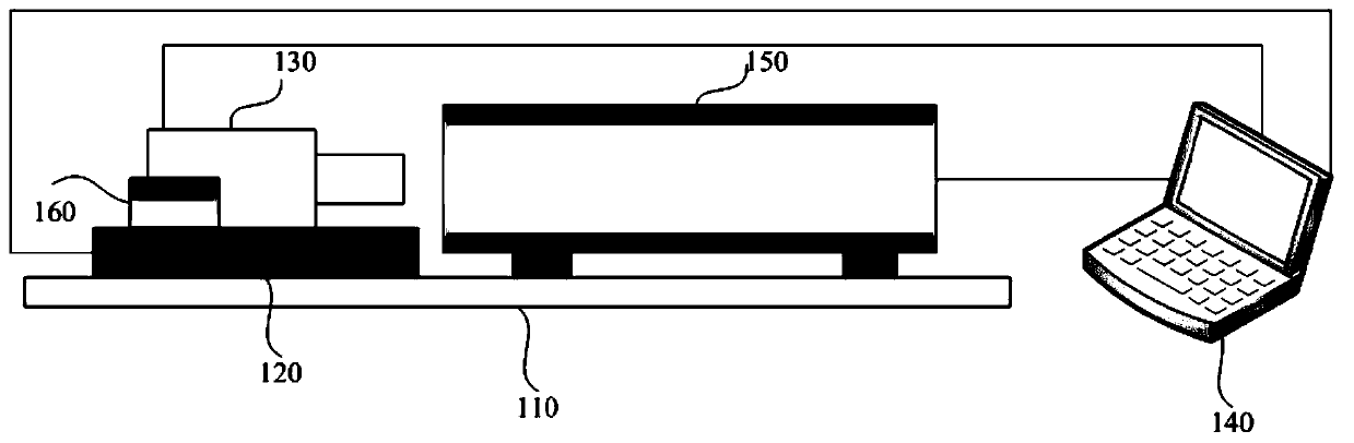
[0030] see figure 1 , is a schematic structural diagram of an instrument autonomous alignment device in a starlight simulation test provided by the present invention, including: an optical shock isolation platform 110, a three-dimensional turntable 120, a star sensor 130, a starlight simulation control computer 140, and a starlight simulator 150. The star sensor 130 is fixed at the central position of the three-dimensional turntable 120, the three-dimensional turntable 120 and the starlight simulator 150 are installed on the optical shock isolation platform 110, and the center of the entrance pupil of the star sensor 130 is At the same height as the center of the exit pupil of the starlight simulator 150 , the three-dimensional turntable 120 , the star sensor 130 and the starlight simulator 150 are connected to the starlight simulation control computer 140 through signals.

[0031] In some preferred embodiments, the shock-isolation platform 110 can be an air-floating shock-iso...

Embodiment 2

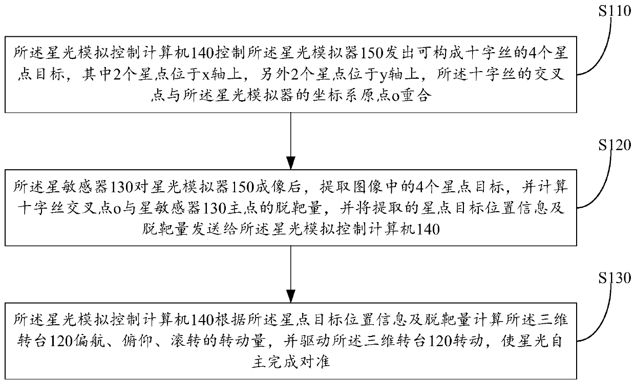
[0037] see figure 2 , the alignment method of the instrument autonomous alignment device in the starlight simulation test provided by the embodiment of the present invention, comprising the following steps:

[0038]Step S110: the starlight simulation control computer 140 controls the starlight simulator 150 to send out 4 starpoint targets that can form a crosshair, wherein 2 starpoints are located on the x-axis, and the other 2 starpoints are located on the y-axis. The intersection point of the crosshairs coincides with the origin o of the coordinate system of the starlight simulator.

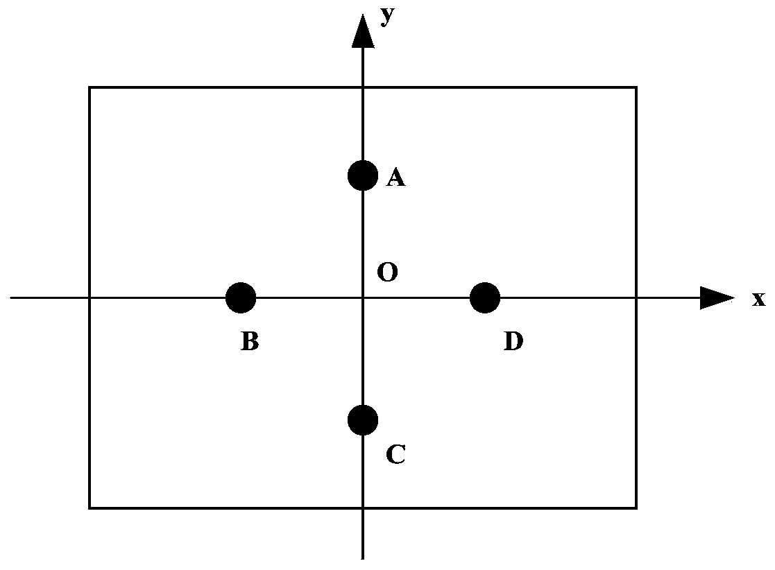
[0039] Specifically, assuming that the field of view of the star sensor 130 is (θ, δ), the starlight simulator 130 takes the optical axis as the z direction, and the origin of the xoy plane as O(0, 0), respectively simulates two distances on the x-axis distant stars, such as Simulate two star points on the y axis, such as A total of 4 star points A, B, C, D, the star point image sent by...


PUM


Abstract

The invention provides an instrument autonomous alignment device in a starlight simulation test and an alignment method. According to the instrument autonomous alignment device and the alignment method, the alignment function can be completed autonomously before a simulation test, and human participation is not needed; the alignment process is controlled by means of a starlight simulation computer, and a three-dimensional turntable and a star sensor fixing tool can adapt to tested equipment in a large size range, so that the influence on the tested equipment is small; the instrument autonomousalignment device and the alignment method can ensure that the attitude information output by the star sensor and the attitude information of a starlight simulator are kept consistent in the testing process, so that the testing precision and the testing efficiency are ensured.

Description

technical field [0001] The invention relates to the technical field of celestial navigation, in particular to an instrument autonomous alignment device and alignment method in starlight simulation testing. Background technique [0002] The star sensor is the most accurate and most commonly used attitude measurement sensor in starlight navigation, and it is a device for determining the attitude by observing the starlight vector. It is impossible to shoot real-time starry sky in the process of equipment development and testing, and the shooting starry sky cannot cover the whole sky area, so the dynamic starlight simulator has become the main equipment for the ground function test of the star sensor. The dynamic starlight simulator is mainly used to test the all-day autonomous recognition success rate and tracking ability of the star sensor. When using the starlight simulator for hardware-in-the-loop simulation tests, the positional relationship between the starlight simulator ...

Claims


Application Information

Patent Timeline
IPC IPC(8): G01C25/00
CPCG01C25/00
Inventor 张磊何昕魏仲慧吕游王军穆治亚孟庆华何家维
Owner CHANGCHUN INST OF OPTICS FINE MECHANICS & PHYSICS CHINESE ACAD OF SCI
Why Eureka
Try Eureka