
Cubesat two-dimensional centroid adjusting method

An adjustment method and a two-dimensional center of mass technology, applied in the field of cube stars, can solve the problems of complex operation, high machining accuracy requirements, failure of fast orbit maneuvering tasks, etc., and achieve the effect of convenient use and simple structure

Active Publication Date: 2019-12-20
NANJING UNIV OF SCI & TECH
View PDF6 Cites 5 Cited by
  • Summary
  • Abstract
  • Description
  • Claims
  • Application Information

AI Technical Summary

Problems solved by technology

The deviation of the center of mass of the satellite system will lead to a deviation between the actual principal axis of inertia and the geometric longitudinal axis. This is one of the factors that cause the thrust eccentricity of the solid rocket thruster. The thrust eccentric moment will cause the satellite attitude to flip, thus making the rapid orbit maneuver mission fail.
The existing centroid adjustment methods include inclined platform method, multi-point support method, etc. Most of these methods demonstrate the feasibility of the method from the perspective of theoretical analysis, the required centroid adjustment device is complicated, the machining accuracy is high, and the test calibration process is cumbersome
For example, the patent CN109540384A proposes a two-dimensional center of mass measurement device and method based on the principle of moment balance. It is necessary to process the corresponding tooling for the measured object. The center of mass adjustment structure is huge and the operation is complicated. The calibration process requires the center of mass standard parts to adjust the center of mass measurement system. check

Method used


Image

  • Cubesat two-dimensional centroid adjusting method
  • Cubesat two-dimensional centroid adjusting method
  • Cubesat two-dimensional centroid adjusting method

Examples


Embodiment Construction

[0024] The implementation of the present invention will be described in detail below in conjunction with specific embodiments.

[0025] A method for adjusting the two-dimensional center of mass of a cube star, comprising the following steps:

[0026] Step 1: setting a horizontal platform, and adjusting the surface of the horizontal platform to the level through the level adjustment mechanism;

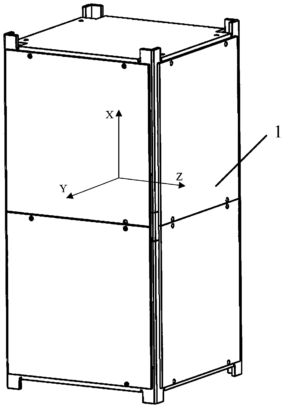
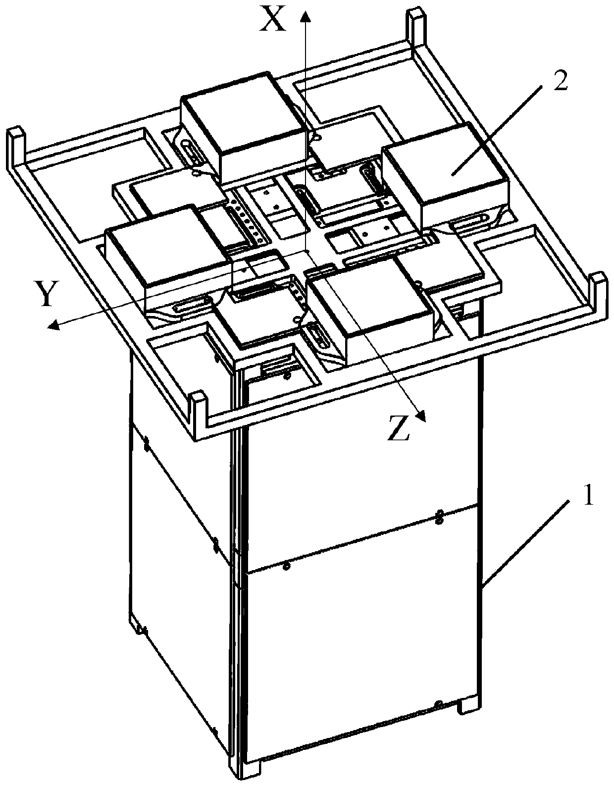
[0027] Step Two: Combine figure 1 , establish CubeSat 1 body coordinate system, set up three-axis accelerometer body coordinate system, the coordinate axes of described three-axis accelerometer body coordinate system are parallel to each other according to the coordinate axes of CubeSat body coordinate system, and described CubeSat body coordinate system is with Cube, the centroid of 1 is the origin of coordinates, set the forward direction and reverse direction of the cube star to +X and -X respectively, and set the direction of the cube star to the sky and the ground to the +Z and -Z...


PUM


Abstract

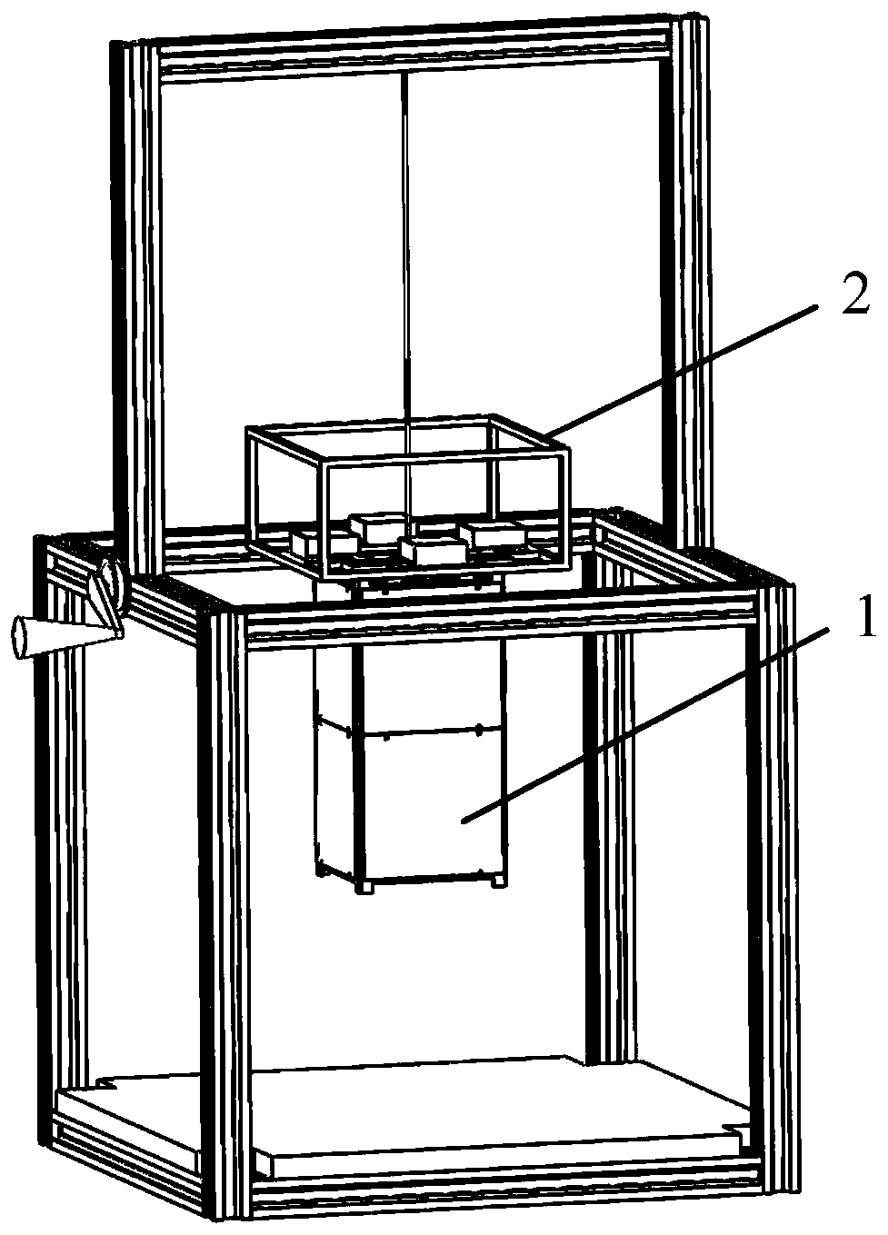
The invention discloses a cubesat two-dimensional centroid adjusting method. The method comprises the following steps of step one, adjusting an upper surface of a horizontal table board to horizontalthrough a horizontal adjusting mechanism; step two, establishing a satellite body coordinate system and a triaxial accelerometer body coordinate system; step three, placing a triaxial accelerometer measurement module on the horizontal table board, and calibrating a triaxial accelerometer; step four, suspending the triaxial accelerometer measurement module, and adjusting the centroid of the measurement module to a center of form location; step five, installing the triaxial accelerometer measurement module on the top of the cubesat; step six, suspending the cubesat through a suspending mechanism, and reading a measurement value of the triaxial accelerometer measurement module in the premise that the satellite is stable, and judging a centroid offset direction and an offset location size; andstep seven, adjusting the cubesat to the geometric longitudinal axis location through the centroid adjusting module. The centroid adjusting method disclosed by the invention is high in precision, good in practicability and convenience.

Description

technical field [0001] The invention relates to the technical field of cube stars, in particular to a method for adjusting a two-dimensional center of mass of a cube star. Background technique [0002] With the rapid development of information technology and miniaturization technology, cube satellites are showing a new trend of rapid development in the field of space science, because they have low cost, batch production, rapid launch of multiple satellites with one arrow, and rapid networking that cannot be compared with traditional large satellites. The application prospects in the military and commercial fields have attracted great attention from all countries, and are regarded as the commanding heights of technological and economic development in the aerospace field. "Clustering" and "distributed" applications require micro-nano satellites to have strong orbital maneuverability. The application of solid rocket thrusters to cube satellites has many advantages, and is usua...

Claims


Application Information

Patent Timeline
IPC IPC(8): G01M1/12
CPCG01M1/125
Inventor 钱鹏俊胡远东陆正亮
Owner NANJING UNIV OF SCI & TECH
Learn More