Shock tunnel with isolation device

A shock tunnel and isolation device technology, applied in the field of shock tunnels, shock tubes and shock tunnels, can solve the problems of test gas pollution, shortened test time, and inability to carry out tests normally, and achieve the purpose of suppressing combustion , Inhibit the burning of the contact surface and improve the reliability of the test

Pending Publication Date: 2019-12-20
中国空气动力研究与发展中心超高速空气动力研究所
View PDF0 Cites 15 Cited by
  • Summary
  • Abstract
  • Description
  • Claims
  • Application Information

AI Technical Summary

Problems solved by technology

[0005] In order to obtain a test gas with higher parameters, gas such as detonation premixed gas, combustion products, hydrogen, hydrogen and nitrogen mixture, etc. may be used as driving gas in the test. At this time, the contact surface between gas and air is likely to It will burn, which may eventually lead to shortened test time, test gas pollution, etc., and even lead to the failure of normal test

Method used


Image

  • Shock tunnel with isolation device

Examples


Embodiment 1

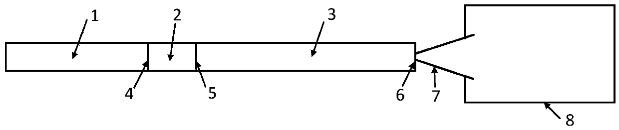
[0026] The working process of the shock tunnel with isolation device of the present invention is as follows:

[0027] Before the test, the driving section 1 is filled with high-pressure gas as the driving gas; the driven section 3 is initially filled with the test gas air, and the isolation section 2 is initially filled with the isolation gas nitrogen, and the driven section 3 and the isolation section 2 The initial inflation pressure is the same. During the test, when the high-pressure gas breaks through the main diaphragm 4, the high-pressure gas will first push the nitrogen in the compression isolation section 2 to generate the first shock wave that propagates downstream, and the nitrogen will break through the isolation after being pressurized, heated and accelerated by the shock wave Diaphragm 5 generates a second shock wave that propagates downstream. The shock wave pushes and compresses the air in the driven section 3, and generates a high-temperature and high-pressure ...


PUM


Abstract

The invention discloses a shock tunnel with an isolation device. The shock tunnel with the isolation device disclosed by the invention comprises a driving section, an isolation section, a driven section, a spray pipe and a test section, which are sequentially connected from front to back, wherein a main membrane is installed between the driving section and the isolation section, an isolation membrane is installed between the isolation section and the driven section, and a throat membrane is installed between the driven section and the spray pipe. According to the shock tunnel with the isolation device disclosed by the invention, a segment of isolation section filled with nitrogen is added in a pipe body of the shock tunnel for isolating the flue gas in the driving section from the in the driven section, so as to suppress contact surface combustion and to improve the test reliability of the shock tunnel.

Description

technical field [0001] The invention belongs to the technical field of shock tubes and shock tunnels, and in particular relates to a shock tunnel with an isolation device. Background technique [0002] Shock tubes and shock tunnels are experimental devices that generate high-temperature and high-pressure airflow. Since the shock tube can easily heat, pressurize and accelerate the gas to a very high parameter, it is widely used in aerospace, aviation, explosion engineering, chemistry and physics and other fields. [0003] A conventional shock tube includes a driving section and a driven section connected sequentially from front to back. The driving section and the driven section are separated by a main diaphragm, and the two sides of the main diaphragm are filled with gases of different pressures; That section is called the low-pressure section, also known as the driven section, and the driven section is filled with test gas; the section with higher pressure is called the hi...

Claims


Application Information

Patent Timeline
Patent Type & Authority Applications(China)
IPC IPC(8): G01M9/02G01M9/04
CPCG01M9/02G01M9/04
Inventor 李贤吴里银张扣立廖振洋钟涌
Owner 中国空气动力研究与发展中心超高速空气动力研究所
Why Eureka
Try Eureka