Flow table system for air flow debugging of gas turbine

A technology of air flow and gas turbine, applied in the direction of gas turbine engine testing, jet engine testing, engine testing, etc., can solve problems such as unsatisfactory engine requirements, improve test accuracy and test efficiency, improve recording efficiency, and improve intelligence Effect

Pending Publication Date: 2019-12-20
楼蓝科技(江苏)有限公司
View PDF0 Cites 5 Cited by
  • Summary
  • Abstract
  • Description
  • Claims
  • Application Information

AI Technical Summary

Problems solved by technology

In order to meet the performance requirements, the requirements for air flow debugging in the process of component processing have also been further increased, and the current domestic equipment cannot meet the needs of the engine

Method used


Image

  • Flow table system for air flow debugging of gas turbine
  • Flow table system for air flow debugging of gas turbine
  • Flow table system for air flow debugging of gas turbine

Examples


Embodiment

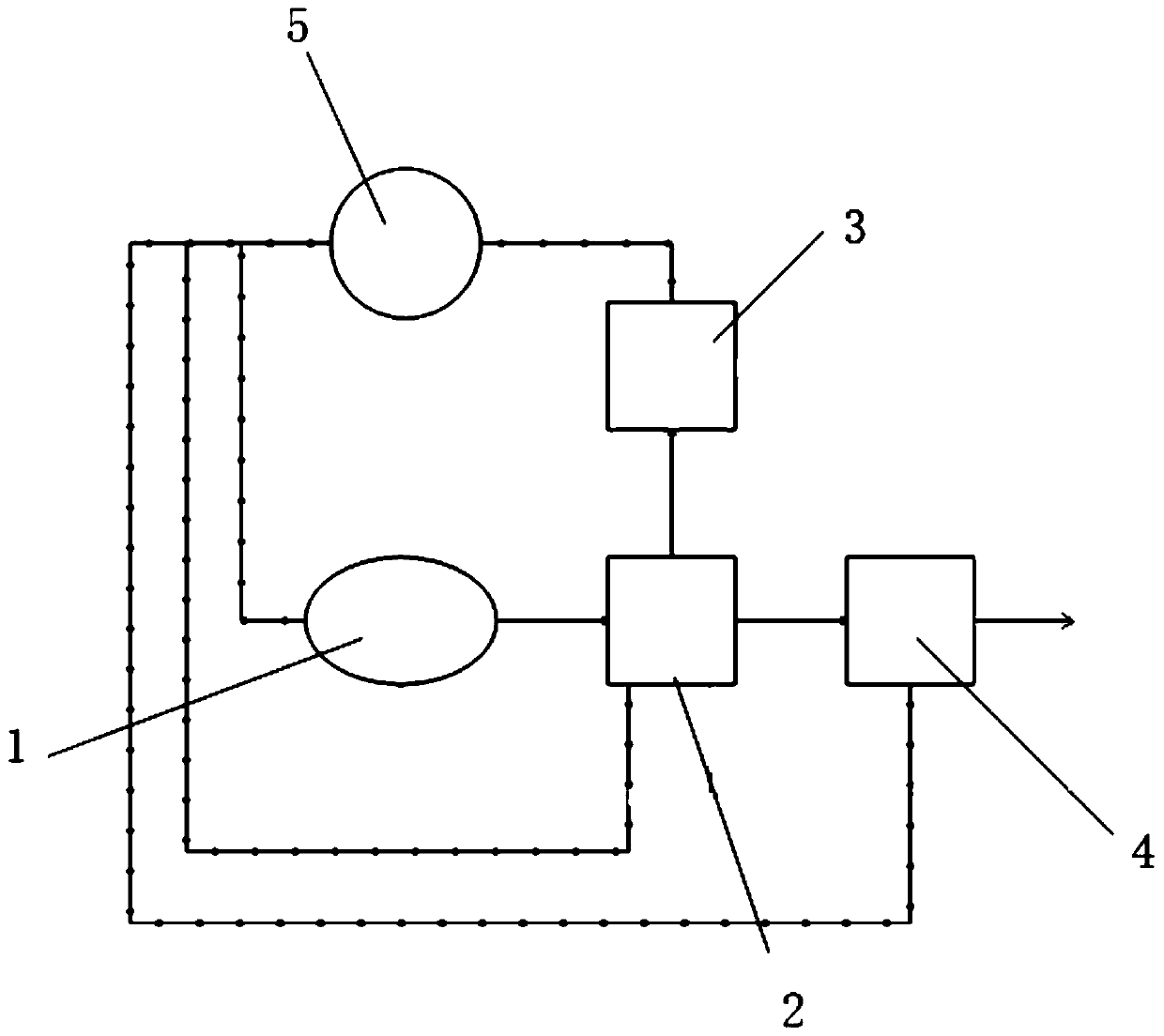
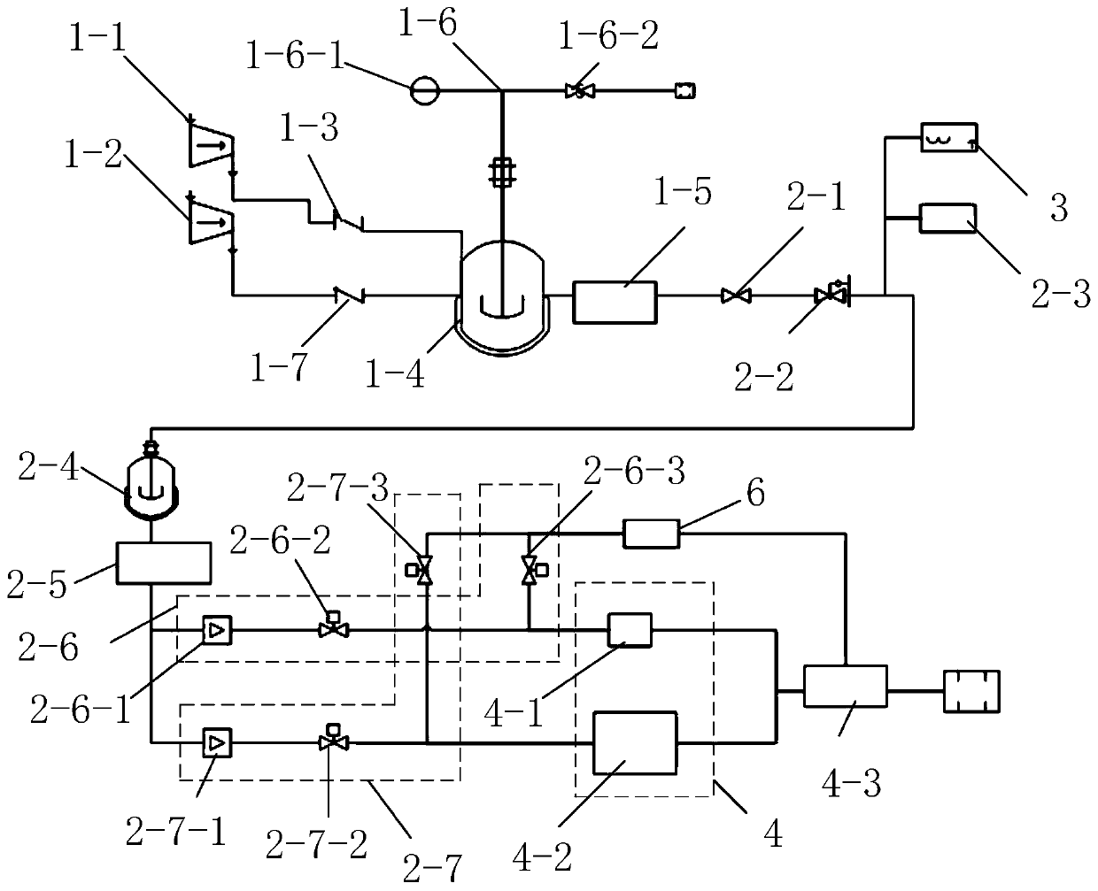
[0050] Such as figure 1 , figure 2 and image 3 as shown,

[0051] A flow table system for gas turbine air flow debugging, comprising a gas station mechanism 1, a pressure control mechanism 2, a temperature measurement mechanism 3, an air flow measurement mechanism 4 and a computer measurement and control mechanism 5, the output end of the gas station mechanism 1 is connected to the The input end of the pressure control mechanism 2 is connected, the output end of the pressure control mechanism 2 is connected with the input end of the temperature measurement mechanism 3, and the output end of the pressure control mechanism 2 is also connected with the input end of the air flow measurement mechanism 4, so The output ends of the pressure control mechanism 2, the temperature measurement mechanism 3 and the air flow measurement mechanism 4 are all connected to the recovery end of the gas station mechanism 1, and the gas station mechanism 1, the pressure control mechanism 2, the ...

Embodiment 1

[0053] According to the above-mentioned embodiment, the gas station mechanism is further limited. The gas station mechanism 1 includes a low-pressure compressor 1-1, a high-pressure compressor 1-2, a first one-way valve 1-3, a second one-way valve 1-7. The gas storage tank 1-4 and the crude air filter 1-5 are composed. The low-pressure air compressor 1-1 is connected to the air storage tank 1-4 through the first one-way valve 1-3. The high-pressure air compressor The machine 1-2 is connected to the air storage tank 1-4 through the second one-way valve 1-7, and the output end of the air storage tank 1-4 is connected with the input end of the crude air filter 1-5, and the crude air The output terminals of the consideration 1-5 are connected with the input terminals of the pressure control mechanism 2.

[0054] The above-mentioned coarse air filter refers to a filter with a larger particle size of suspended solids that can be filtered.

[0055] In the first embodiment above, the...

Embodiment 2

[0058] According to the above embodiment, the pressure control mechanism is further limited. The pressure control mechanism 2 is composed of a pneumatic shut-off valve 2-1, a pressure reducing valve 2-2, a pressure sensor 2-3, a stabilized pressure gas storage tank 2-4, The precision air filter 2-5, the first pressure control device 2-6 and the second pressure control device 2-7 are composed, the input end of the pneumatic stop valve 2-1 is connected with the output end of the gas station mechanism 1, and the The output end of the pneumatic shut-off valve 2-1 is connected to the input end of the pressure reducing valve 2-2, and the output end of the pressure reducing valve 2-2 is connected to the input end of the pressure-stabilizing gas storage tank 2-4, and the pressure-stabilizing valve The output end of the pressure storage tank 2-4 is connected to the input end of the precision air filter 2-5, and the output end of the precision air filter 2-5 is connected to the input end...


PUM


Abstract

The invention relates to a flow table system for air flow debugging of a gas turbine. The flow table system comprises an air station mechanism, a pressure control mechanism, a temperature measurementmechanism, an air flow measurement mechanism and a computer measurement and control mechanism, wherein the output end of the gas station mechanism is connected to the input end of the pressure controlmechanism; the pressure control mechanism is connected to the input end of the temperature measurement mechanism; the output end of the pressure control mechanism is connected to the input end of theair flow measurement mechanism; the output end of the air flow measurement mechanism is connected to the atmospheric environment; and the air station mechanism, the pressure control mechanism, the temperature measurement mechanism and the data feedback end of the air flow measurement mechanism are connected to the input end of the computer measurement and control mechanism. Modules of the flow table system can work independently and be maintained independently, and the flow table system is prone to transformation and upgrade of measurement of different types of parts.

Description

technical field [0001] The invention belongs to the technical field of air flow of aviation gas turbines, and in particular relates to a flow table system for debugging the air flow of gas turbines. Background technique [0002] In the aeroengine system, the core machine is the main core unit, which consists of three parts: compressor, combustion chamber and turbine. The air compressed by the compressor enters the combustor and the turbine and is divided into multiple flow paths, including air for cooling and air for combustion or work. The air volume used by each part is distributed by some designed holes, channels, etc. The accuracy of air flow distribution affects the efficiency and cooling safety of the gas turbine. During the design and test of the combustor and turbine, some important components such as the main swirler, turbine guide vane, and flame tube need to be adjusted for air flow to confirm whether the air flow through the manufactured holes or channels meets ...

Claims


Application Information

Patent Timeline
Patent Type & Authority Applications(China)
IPC IPC(8): G01M15/02G01M15/14
CPCG01M15/02G01M15/14
Inventor 刘六九孙杰邱志恒李正伟丰雷鸣孙威威
Owner 楼蓝科技(江苏)有限公司
Why Eureka
Try Eureka