Supercharge Your Innovation With Domain-Expert AI Agents!

Display panel and display module

A display panel and display module technology, which is applied to instruments, nonlinear optics, optics, etc., can solve problems such as liquid crystal leakage of display panels, and achieve the effect of ensuring sealing and improving yield.

Active Publication Date: 2021-02-26
WUHAN CHINA STAR OPTOELECTRONICS TECH CO LTD
View PDF10 Cites 0 Cited by
  • Summary
  • Abstract
  • Description
  • Claims
  • Application Information

AI Technical Summary

Problems solved by technology

[0005] This application provides a display panel and a display module to solve the technical problem of liquid crystal leakage when the existing display panel is cut

Method used


Image

  • Display panel and display module
  • Display panel and display module
  • Display panel and display module

Examples


Embodiment Construction

[0042] The following descriptions of the various embodiments refer to the accompanying drawings to illustrate specific embodiments that the present application can be used to implement. The directional terms mentioned in this application, such as [top], [bottom], [front], [back], [left], [right], [inside], [outside], [side], etc., are for reference only The orientation of the attached schema. Therefore, the directional terms used are used to illustrate and understand the application, but not to limit the application. In the figures, structurally similar elements are denoted by the same reference numerals.

[0043] When the display panel motherboard is cut, the black photoresist in the cutting area has weak adhesion to the substrate, so the cutting force generated during cutting is easy to separate the black photoresist from the color filter substrate, and the color filter The substrate is separated from the array substrate, resulting in liquid crystal leakage in the display ...


PUM


Abstract

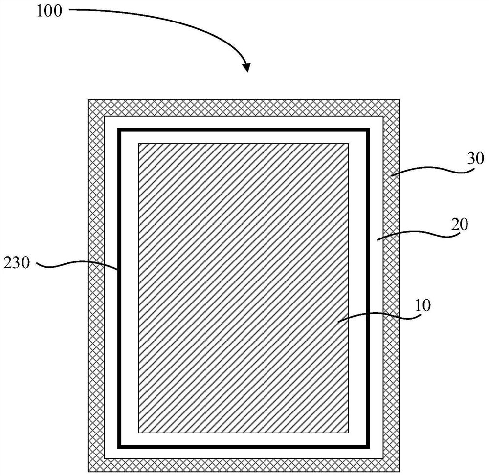
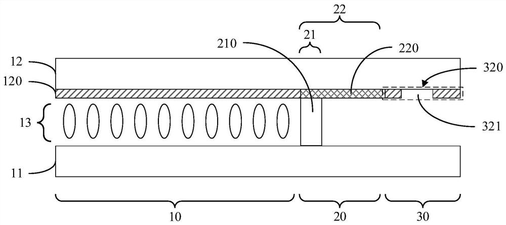
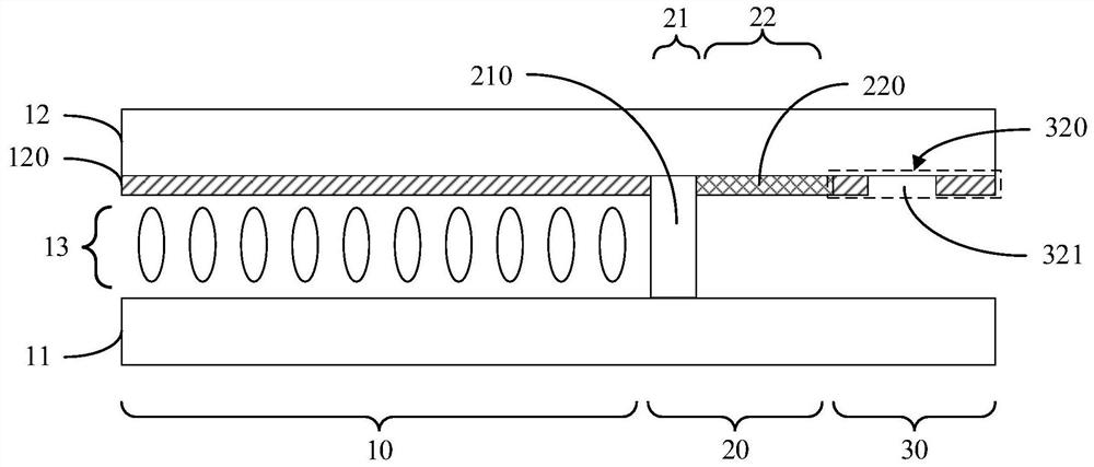
Provided are a display panel and a display module. The display panel comprises a display region, a protection region surrounding the display region, and a cutting region positioned at the periphery of the protection region. A first substrate and a second substrate are provided in the display region. A patterned first light-shielding layer is provided within the protection region. A patterned second light-shielding layer is provided within the cutting region. The first light-shielding layer, the second light-shielding layer and a color filter layer of the first substrate or the second substrate are arranged in the same layer.

Description

technical field [0001] The present application relates to the display field, in particular to a display panel and a display module. Background technique [0002] In the manufacturing process of the existing Flat Plate Display (FPD), the mother board of the display panel is involved in multiple cutting processes to obtain the final display panel. [0003] Existing display panel motherboards include a cutting line between two adjacent display panels. The cutting line is generally distributed with a light-shielding layer and substrates on both sides of the light-shielding layer. The light-shielding layer is generally composed of black photoresist. When cutting the motherboard of the display panel, since the black photoresist is an organic material, and the bonding performance of the corresponding substrate is weak, the cutting force generated during cutting is easy to separate the black photoresist from the color film substrate, and the color film substrate is easily separated....

Claims


Application Information

Patent Timeline
Patent Type & Authority Patents(China)
IPC IPC(8): G02F1/1335G02F1/1333
CPCG02F1/1333G02F1/133512G02F1/133388
Inventor 余朋飞
Owner WUHAN CHINA STAR OPTOELECTRONICS TECH CO LTD
Features
  • R&D
  • Intellectual Property
  • Life Sciences
  • Materials
  • Tech Scout
  • Unparalleled Data Quality
  • Higher Quality Content
  • 60% Fewer Hallucinations
Learn More