Multipurpose combined protection transformer

A transformer and multi-purpose technology, applied in the field of transformers, can solve the problems of complex installation process, malfunction, large floor space, etc., and achieve the effects of safe and reliable operation, convenient installation and disassembly, and convenient operation.

Active Publication Date: 2019-12-20
湖南国丰电力设备有限公司
View PDF7 Cites 0 Cited by
  • Summary
  • Abstract
  • Description
  • Claims
  • Application Information

AI Technical Summary

Problems solved by technology

[0003] In order to ensure that the transformer will not be damaged under the influence of lightning shock and external short-circuit shock, and can still work normally, the transformer is usually installed with protective devices such as lightning arresters, drop fuses, and circuit breakers. These protective devices are generally installed Outside the transformer, the installation process is complicated and the floor area is large, and the drop-out fuse is easily affected by wind, rain, snow, hail and other weather factors and vibrations, resulting in malfunctions and power outages caused by non-fault factors
In areas with high altitude and high pollution where the air is thin, the maintenance of the transformer is difficult due to harsh weather conditions, and the air is thin, the air insulation strength is low, and corona is easy to occur around the bushing. It is more troublesome for internal maintenance

Method used


Image

  • Multipurpose combined protection transformer
  • Multipurpose combined protection transformer
  • Multipurpose combined protection transformer

Examples


Embodiment 1

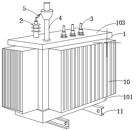
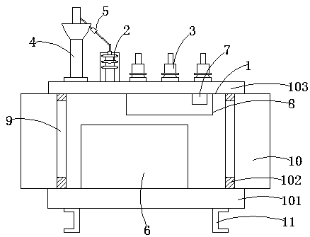
[0024] like Figure 1-2 As shown, a multi-purpose combined protection transformer includes a transformer body 1. The transformer body 1 includes a fixed base 101. The fixed base 101 is a cuboid structure. The four edges of the upper end of the fixed base 101 are vertically installed with protective side plates 102. The protective side plates The upper end of 102 is provided with a top plate 103 horizontally, and a high-voltage bushing 2 and a low-voltage bushing 3 are installed above the top plate 103. A surge arrester 4 is installed on one side of the high-voltage bushing 2, and a fuse is arranged between the surge arrester 4 and the high-voltage bushing 2 5. The upper end of the fixed base 101 is located inside the protective side plate 102, and a transformer oil tank 6 is installed. An installation port 9 is provided, and the installation port 9 penetrates into the inner cavity of the transformer body 1 , a cooling fin 10 is installed on the installation port 9 , and two in...

Embodiment 2

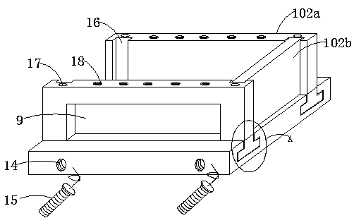
[0027] like Figure 1-5 As shown, a multi-purpose combined protection transformer includes a transformer body 1. The transformer body 1 includes a fixed base 101. The fixed base 101 is a cuboid structure. The four edges of the upper end of the fixed base 101 are vertically installed with protective side plates 102. The protective side plates The upper end of 102 is provided with a top plate 103 horizontally, and a high-voltage bushing 2 and a low-voltage bushing 3 are installed above the top plate 103. A surge arrester 4 is installed on one side of the high-voltage bushing 2, and a fuse is arranged between the surge arrester 4 and the high-voltage bushing 2 5. The upper end of the fixed base 101 is located inside the protective side plate 102, and a transformer oil tank 6 is installed. An installation port 9 is provided, and the installation port 9 penetrates into the inner cavity of the transformer body 1 , a cooling fin 10 is installed on the installation port 9 , and two in...


PUM


Abstract

The invention provides a multipurpose combined protection transformer, and relates to the technical field of transformers. The multipurpose combined protection transformer comprises a transformer body, wherein the transformer body comprises a fixed base; protection side plates are vertically mounted at the positions of four edges of the upper end of the fixed base; a top plate is horizontally arranged at the upper ends of the protection side plates; a high-pressure sleeve and a low-pressure sleeve are mounted above the top plate; a lightning arrester is mounted on one side of the high-pressuresleeve; a fuse is arranged between the lightning arrester and the high-voltage sleeve; and two mounting frames are arranged at the lower end of the fixed base. In the multipurpose combined protectiontransformer, before the lightning arrester is installed in the high-voltage sleeve, damage caused by lightning can be effectively reduced, and safe operation of the transformer is maintained; the fuse is installed between the lightning arrester and the high-voltage sleeve, the fuse protects the transformer from damage caused by overcurrent, and the safety of the transformer is protected; and in addition, the whole device is stable in performance, and safe and reliable in action, no misoperation is generated, the whole device is convenient to install and disassemble, and the transformer is convenient to maintain.

Description

technical field [0001] The invention relates to the technical field of transformers, in particular to a multi-purpose combined protection transformer. Background technique [0002] Transformer is a device that uses the principle of electromagnetic induction to change AC voltage. The main components are primary coil, secondary coil and iron core (magnetic core). The main functions are: voltage transformation, current transformation, impedance transformation, isolation, voltage stabilization (magnetic saturation transformer), etc. According to the use, it can be divided into: power transformers and special transformers (electric furnace transformers, rectifier transformers, power frequency test transformers, voltage regulators, mining transformers, audio transformers, intermediate frequency transformers, high frequency transformers, impact transformers, instrument transformers, electronic transformers , reactors, transformers, etc.). Circuit symbols often use T as the begi...

Claims


Application Information

Patent Timeline
Patent Type & Authority Applications(China)
IPC IPC(8): H01F27/40H01F27/06H01F27/08H01F27/02H01F27/29
CPCH01F27/402H01F27/06H01F27/08H01F27/025H01F27/02H01F27/29H01F2027/404Y02A30/14
Inventor 李新国
Owner 湖南国丰电力设备有限公司
Why Eureka
Try Eureka