Charging method and system

A charging method and charging power technology, which is applied in the direction of measuring electricity, current collectors, electric vehicles, etc., can solve the problems of prolonged investment recovery period of energy storage power stations, affecting the cycle life of battery packs, and insufficient charging power of battery packs, etc., to achieve shortening Investment recovery period, flexible charging method, and the effect of improving charging efficiency

Inactive Publication Date: 2019-12-20
ZHEJIANG NARADA POWER SOURCE CO LTD +1
View PDF7 Cites 3 Cited by
  • Summary
  • Abstract
  • Description
  • Claims
  • Application Information

AI Technical Summary

Problems solved by technology

[0003] At present, the charging method commonly used in energy storage power stations is constant power charging or constant power constant voltage charging. For energy storage power stations using lead-acid batteries When the charging voltage reaches the end-of-charging voltage set by the battery pack terminal of the energy storage power station, the energy storage bidirectional converter switches to constant voltage charging, and the battery continues to charge at this time. This charging method can better solve the problem of insufficient charging power of the battery pack. However, for energy storage power stations using lithium batteries as battery packs, due to the characteristics of the batteries, if they continue to use constant voltage charging, it will seriously affect the safety performance of the batteries. Therefore, only constant power charging methods can be used, that is, the charging process In this case, i

Method used


Image

  • Charging method and system
  • Charging method and system
  • Charging method and system

Examples


Example Embodiment

[0025] The following will clearly and completely describe the technical solutions in the embodiments of the present invention with reference to the accompanying drawings in the embodiments of the present invention. Obviously, the described embodiments are only some, not all, embodiments of the present invention. Based on the embodiments of the present invention, all other embodiments obtained by persons of ordinary skill in the art without making creative efforts belong to the protection scope of the present invention.

[0026] Unless otherwise defined, all technical and scientific terms used herein have the same meaning as commonly understood by one of ordinary skill in the technical field of the invention. The terms used herein in the description of the present invention are for the purpose of describing specific embodiments only, and are not intended to limit the present invention.

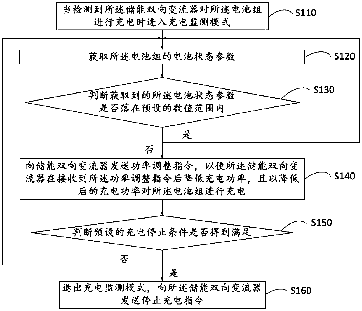
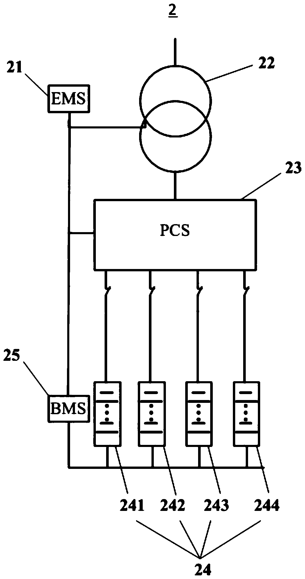
[0027] Please also see figure 1 and figure 2 ,in, figure 1 is a schematic flow chart of...


PUM


Abstract

The invention discloses a charging method and system, which are applied to an energy storage power station. The charging method comprises the steps of entering a charging monitoring mode when an energy storage bidirectional converter is detected to charge a battery pack; obtaining battery state information, wherein battery state parameters of the battery pack are detected; and performing batterycharging control, wherein whether the detected battery state parameters are within a preset numerical range or not is judged, if yes, the step of obtaining the battery state information is carried out, and if not, a power adjustment instruction is sent to the energy storage bidirectional converter for enabling the energy storage bidirectional converter to reduce charging power after receiving thepower adjustment instruction and charge the battery pack with the reduced charging power; and whether preset charging stop conditions are met or not is judged, if not, the step of obtaining the battery state information is carried out, and if yes, the charging monitoring mode exits and a charging stop instruction is sent to the energy storage bidirectional converter. By adopting the scheme, the influence of a charging process on the cycle service life of the battery pack can be reduced.

Description

technical field [0001] The invention relates to the technical field of charging of energy storage power stations, in particular to a charging method and system. Background technique [0002] With the development of society, energy storage technology is ubiquitous in people's lives, and it plays an extremely important role in the power generation side, transmission side, power distribution side, and power consumption side of the power grid. [0003] At present, the charging method commonly used in energy storage power stations is constant power charging or constant power constant voltage charging. For energy storage power stations using lead-acid batteries When the charging voltage reaches the end-of-charging voltage set by the battery pack terminal of the energy storage power station, the energy storage bidirectional converter switches to constant voltage charging, and the battery continues to charge at this time. This charging method can better solve the problem of insuffic...

Claims


Application Information

Patent Timeline
IPC IPC(8): H02J7/00G01R31/388G01R31/389G01R31/392
CPCG01R31/388G01R31/389G01R31/392
Inventor 张楠谭建国吴贤章何选谢云强严广龙
Owner ZHEJIANG NARADA POWER SOURCE CO LTD
Why Eureka
Try Eureka