Supercharge Your Innovation With Domain-Expert AI Agents!

Valve, use of such valve, separator comprising such valve and method of operating the separator

A technology for separators, valve closure, applied in the field of operating separators

Active Publication Date: 2021-05-04
HUSQVARNA AB
View PDF10 Cites 0 Cited by
  • Summary
  • Abstract
  • Description
  • Claims
  • Application Information

AI Technical Summary

Problems solved by technology

[0018] Although a well functioning purge valve is disclosed in WO2009041890A2, there is still room for improvement

Method used


Image

  • Valve, use of such valve, separator comprising such valve and method of operating the separator
  • Valve, use of such valve, separator comprising such valve and method of operating the separator
  • Valve, use of such valve, separator comprising such valve and method of operating the separator

Examples


Embodiment Construction

[0063] In the following description, the valve will be described with reference to its use in a separator that is part of a heavy duty vacuum cleaner useful in a floor grinding environment.

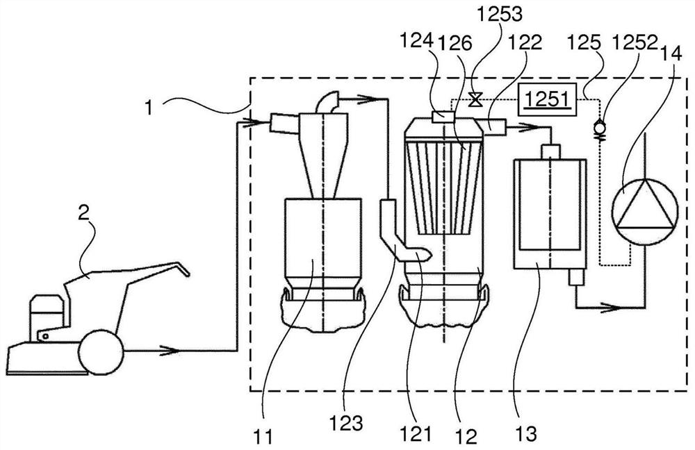
[0064] refer to figure 1 , the system comprises a floor grinder 2, which can be any type of floor grinder with a connector for emptying grinding residues. The system also comprises a heavy-duty vacuum cleaner unit 1 comprising a pre-separator 11 shown as a cyclone; a main separator 12 comprising an inlet 121, an outlet 122, an inlet valve 123, a purge valve 124 and a separator body 126, such as filters. The system also includes a rear splitter 13, such as a HEPA filter, and a suction generator 14, which may include a motor driving a fan to generate airflow.

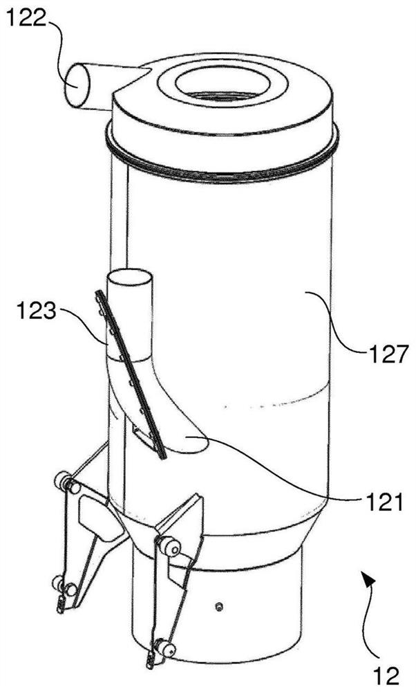
[0065] figure 2 Separator 12 is shown schematically with separator inlet 121 , outlet 122 , inlet valve 123 and housing 127 . Purge valve 124 is also visible at the top of housing 127 .

[0066] refer to Figure 3a-Figure 3b ,...


PUM


Abstract

This document discloses a valve comprising: a main valve closing body arranged on the low pressure side of the valve and movable towards the low pressure side to open; a control body fixedly connected to the main valve closing body to making the position of the main valve closing body fixed relative to the position of the control body; a control chamber, which is partially defined by the control body, whereby the volume of the control chamber is variable relative to the position of the control body; and a control fluid connector, which Used to control the pressure in this control chamber. This document also discloses the use of the valve in a separator for separating dust and debris from a gas flow, a separator comprising such a valve and a method of operating the separator.

Description

technical field [0001] The present disclosure relates to a valve, to the use of such a valve as a cleaning valve for a separator, to a separator comprising such a valve, and to a method of operating a separator. [0002] More specifically, the present disclosure relates to a cleaning valve for a separator, ie to a valve for generating a reverse jet of air through the filter of the separator to clean the filter. Background technique [0003] Separators are used to separate particles (including powders, pellets, debris, etc.) from a fluid stream (such as air, oil, or water, etc.). [0004] Some separators utilize a permeable separator body that traps particles as flow is directed through the separator body. The separator body may take the form of a grate, mesh or filter media. The filter media may comprise a porous material that is desirably permeable to the fluid but impermeable to the particles to be separated. In many applications, the filter material can be a woven or n...

Claims


Application Information

Patent Timeline
Patent Type & Authority Patents(China)
IPC IPC(8): F16K31/126B01D46/00A47L7/00A47L9/20B01D46/24F16K31/128F16K39/02F16K31/06A47L9/00B01D45/00
CPCA47L7/0095A47L9/20B01D46/0087B01D46/0089F16K31/1266F16K31/128F16K39/022F16K31/0624B01D2275/201B01D45/16B01D46/2414B01D46/86B01D46/71B01D50/20B01D46/04F16K31/126B01D46/70B01D46/4272
Inventor 安德列斯·福格尔贝里
Owner HUSQVARNA AB
Features
  • R&D
  • Intellectual Property
  • Life Sciences
  • Materials
  • Tech Scout
  • Unparalleled Data Quality
  • Higher Quality Content
  • 60% Fewer Hallucinations
Learn More