Biomarker detection method, disease assessment method, biomarker detection device, and biomarker detection program

A technology of biomarker and detection method, applied in the field of biomarker detection, disease judgment, biomarker detection device and biomarker detection program

Pending Publication Date: 2019-12-20
JAPAN SCI & TECH CORP
View PDF8 Cites 2 Cited by
  • Summary
  • Abstract
  • Description
  • Claims
  • Application Information

AI Technical Summary

Problems solved by technology

Examination or image diagnosis at the hospital

Method used


Image

  • Biomarker detection method, disease assessment method, biomarker detection device, and biomarker detection program
  • Biomarker detection method, disease assessment method, biomarker detection device, and biomarker detection program
  • Biomarker detection method, disease assessment method, biomarker detection device, and biomarker detection program

Examples


no. 1 approach

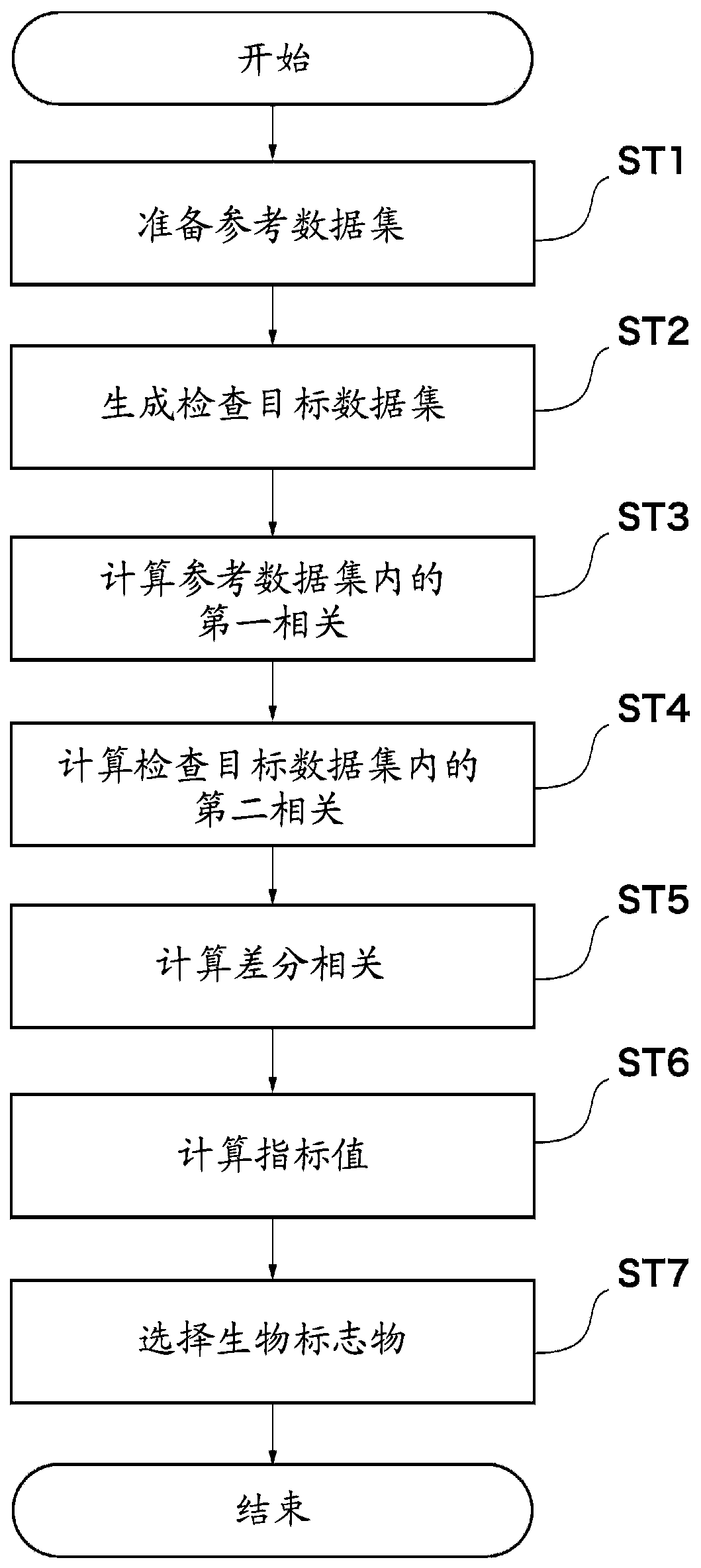
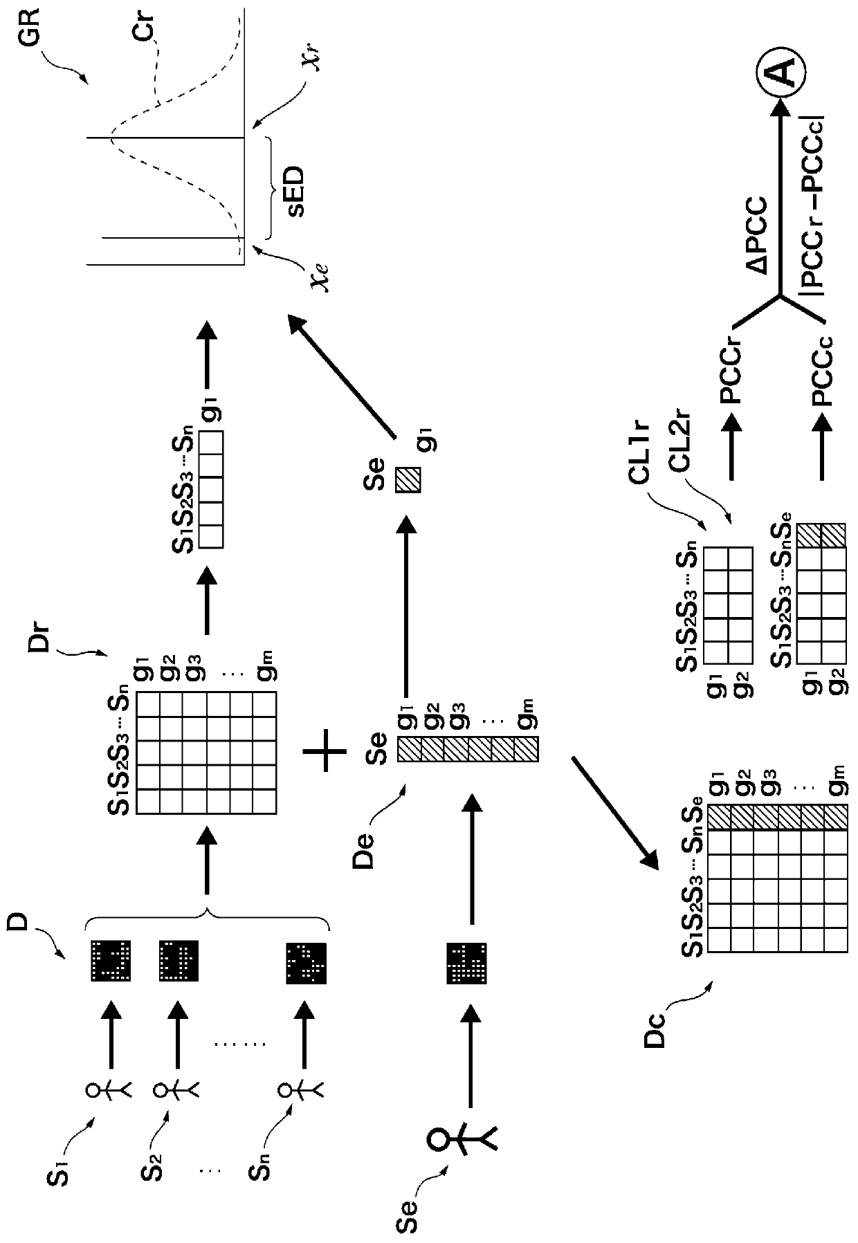
[0032] Below, refer to Figure 2 to Figure 5 The biomarker detection method according to the first embodiment of the present invention will be described. figure 2 is a flowchart for explaining the biomarker detection method according to the first embodiment. image 3 and Figure 4 is a schematic diagram showing the biomarker detection method according to the first embodiment.

[0033] Such as figure 2 As shown, the biomarker detection method according to the first embodiment includes: a step of preparing a reference data set (ST1); a step of generating an inspection target data set (ST2); a step of calculating a first correlation coefficient (ST3); The step of two correlation coefficients (ST4); the step of calculating differential correlation coefficients (ST5); the step of obtaining indexes (ST6); and the step of selecting biomarkers (ST7).

[0034]

[0035] First, prepare the reference data set Dr( image 3 ). The reference dataset Dr is a dataset used as reference ...

no. 2 approach

[0067] Next, a biomarker detection device according to a second embodiment of the present invention will be described. Figure 6 is a block diagram showing a configuration example of the detection device according to the second embodiment. Figure 6 The shown biomarker detection device 1 includes a control unit 10 , a storage unit 11 , a storage unit 12 , an input unit 13 , an output unit 14 and an interface unit 15 .

[0068] The control unit 10 is configured using circuits such as a CPU (Central Processing Unit) and controls the entire detection device 1 . The storage unit 11 includes a magnetic recording device such as HDD (Hard Disk Drive) and a nonvolatile auxiliary recording device such as SSD (Solid State Drive). The storage unit 11 records various programs including the detection program 11a according to the embodiment of the present invention. The detection program 11a includes instructions (codes) for causing the detection device 1 to implement the biomarker detect...

no. 3 approach

[0080] Below, refer to Figure 7 The biomarker detection method according to the third embodiment of the present invention will be described. Figure 7 is a flowchart showing a biomarker detection method according to the third embodiment.

[0081] Such as Figure 7 As shown, the biomarker detection method according to the third embodiment includes a step of acquiring high-throughput data (ST11), a step of selecting differential factors (ST12), a clustering step (ST13) and a step of selecting biomarkers (ST14).

[0082] First, in the step of acquiring high-throughput data (ST11), high-throughput data are obtained from the subject Se at different time points. Specifically, first, living body samples are collected from the subject Se a plurality of times in chronological order. The number of biopsy samples collected is preferably 5 or more, for example. In addition, each time interval may be set to several days, weeks, months or years, or may be, for example, minutes or hour...


PUM


Abstract

A biomarker detection method that includes: a step (ST1) in which a reference data set is prepared on the basis of data for multiple factor items among reference biological data obtained from multiplereference biological objects; a step (ST2) in which a subject data set is generated by adding, to the reference data set, data for multiple factor items among subject biological data obtained from asubject biological object; a step (ST3) in which a first correlation coefficient between the multiple factor items in the reference data set is obtained; a step (ST4) in which a second correlation coefficient between the multiple factor items in the subject data set is obtained; a step (ST5) in which a difference correlation coefficient, which is a difference between the first correlation coefficient and the second correlation coefficient, is obtained; a step (ST6) in which an index based on the difference correlation coefficient is obtained for each of the multiple factor items; and a step (ST7) in which a biomarker is selected on the basis of the index.

Description

technical field [0001] The present invention relates to a biomarker detection method, a disease judgment method, a biomarker detection device, and a biomarker detection method for detecting a biomarker indicating a state of a living body based on data of factor items obtained by measuring a living body program. Background technique [0002] It is known that in the same way as complex systems such as climate systems, ecosystems, and economic systems, when a certain transition point (branch point) is exceeded, the state of the living body (for example, health status, etc.) changes from good or normal (hereinafter referred to as "good" ”) state rapidly changes to a disease state (see Patent Document 1 and Non-Patent Documents 1 to 5). Furthermore, fluctuations are known to increase at transition points in complex systems and there are variables that are strongly correlated with this fluctuation. One of the reasons may be, for example, that the restoring force for stably maint...

Claims


Application Information

Patent Timeline
Patent Type & Authority Applications(China)
IPC IPC(8): G16B15/30C12M1/34G01N33/48C12Q1/68
CPCC12M1/34C12Q1/68G01N33/48G16H50/20G16B50/30G16B30/10G16B40/00G01N2800/60G01N33/57484A61B5/7246G06T7/0012G06T2207/30004
Inventor 陈洛南合原一幸刘小平
Owner JAPAN SCI & TECH CORP
Why Eureka
Try Eureka