Radial flow turbine guide vane structure coupled with non-axisymmetric end walls

A turbine guide vane, non-axisymmetric technology, applied in the direction of the stator, engine components, machine/engine, etc., can solve the problems of large channel vortex size, poor outlet airflow uniformity, etc., and achieve high energy utilization efficiency and secondary flow loss The effect of reducing, reducing intensity

Active Publication Date: 2019-12-24
INST OF ENGINEERING THERMOPHYSICS - CHINESE ACAD OF SCI
View PDF3 Cites 5 Cited by
  • Summary
  • Abstract
  • Description
  • Claims
  • Application Information

AI Technical Summary

Problems solved by technology

[0005] In order to solve the technical problems in the prior art, such as obvious secondary flow on the end wall of the radial flow guide vane with low aspect ratio, relatively large channel vortex size, and poor uniformity of outlet airflow, the present invention proposes a radial flow turbine coupled with a non-axisymmetric end wall. The guide vane structure can effectively control the secondary flow loss of the guide vane end wall of the low-aspect-ratio radial flow turbine, reduce the size of the channel vortex, and improve the uniformity of the outlet airflow, thereby improving the aerodynamic efficiency and working capacity of the radial flow turbine and increasing the radial flow turbine. The utilization efficiency of energy meets the needs of high-efficiency operation of radial turbines and promotes the application of radial turbines in high-efficiency operation systems. This technology makes radial turbines more efficient, and has processing feasibility and broad application prospects.

Method used


Image

  • Radial flow turbine guide vane structure coupled with non-axisymmetric end walls
  • Radial flow turbine guide vane structure coupled with non-axisymmetric end walls
  • Radial flow turbine guide vane structure coupled with non-axisymmetric end walls

Examples


Embodiment Construction

[0033] In order to make the object, technical solution and advantages of the present invention clearer, the present invention will be further described in detail below with reference to the accompanying drawings and examples.

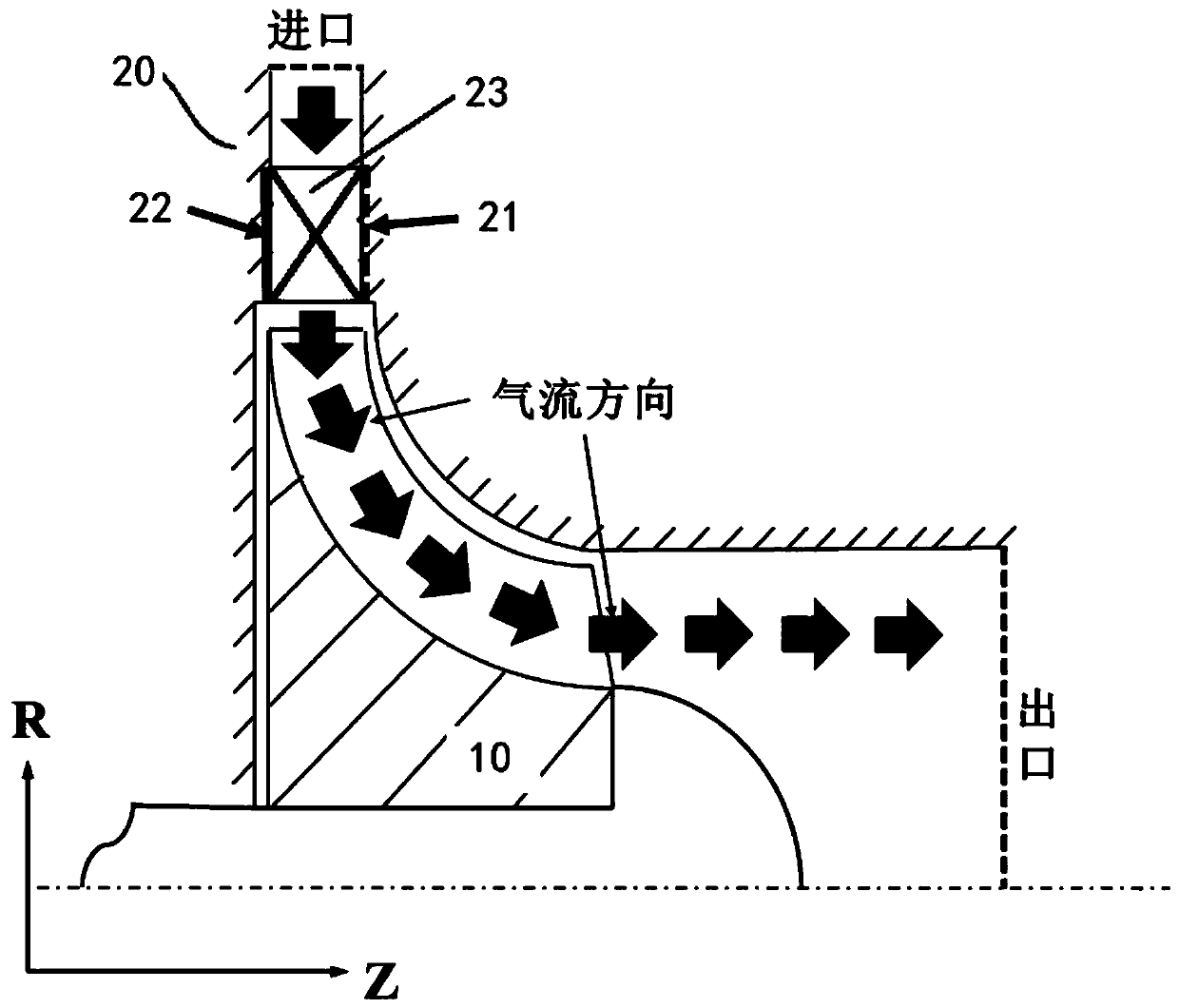
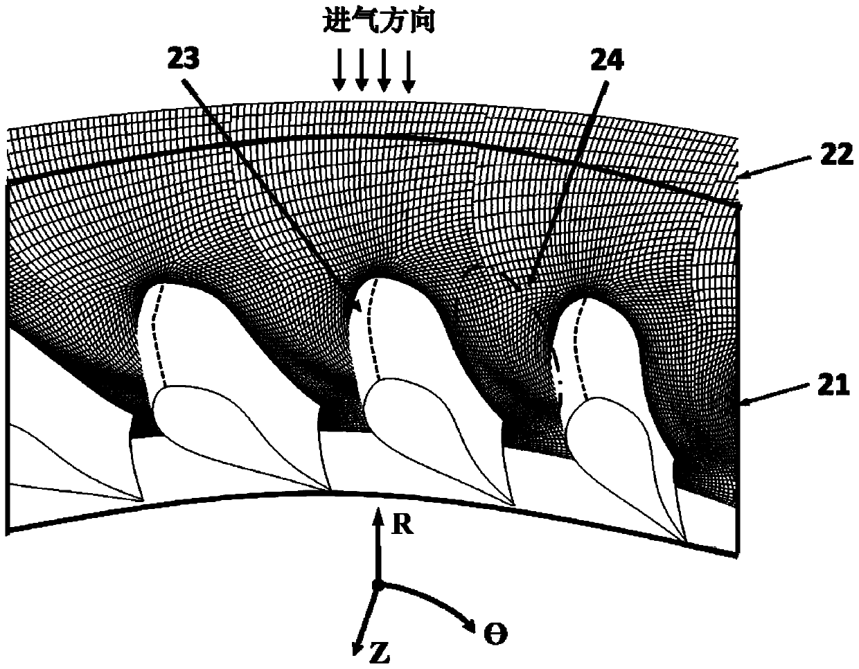
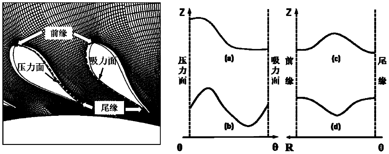
[0034] Such as figure 1 As shown, the radial turbine includes an impeller 10 and a radial turbine vane structure 20 arranged on the periphery of the impeller 10. The radial turbine vane structure 20 includes a front end wall 21, a rear end wall 22, and a front end wall 21 and a rear end wall 22. A plurality of radial flow turbine guide vanes 23 evenly arranged in the circumferential direction, the front end wall 21 and the rear end wall 22 are basically disc-shaped structures, and a flow channel is formed between two adjacent radial flow turbine guide vanes 23. One of the flow channels One side is the pressure surface of a radial turbine vane, and the other side of the flow channel is the suction surface of another radial turbine vane.

[0035] The app...


PUM


Abstract

The invention relates to a radial flow turbine guide vane structure coupled with non-axisymmetric end walls. The radial flow turbine guide vane structure aims to solve the technical problems of remarkable secondary flow of low-span chord ratio runoff guide vane end walls, relatively large channel vortex size, poor outlet air flow uniformity and the like. A non-axisymmetric concave-convex end wallstructure is adopted at each of the front end walls and the rear end walls of radial flow turbine guide vanes and can be matched with the radial flow turbine guide vanes with the three-dimensional configuration to control the flow channel secondary flow loss more effectively. According to the radial flow turbine guide vane structure, a blade lattice is modified, and specifically, the inner surfaces of the front end walls and the rear end walls are correspondingly arranged as the non-axisymmetric concave-convex end wall structures, so that the flow area of each flow channel is changed, and theair flow pressure difference between the pressure surface on one side of each flow channel and the suction surface on the other side of each flow channel is reduced, so that the secondary flow velocity distribution is affected, the formation and development of the channel vortex are delayed, the channel vortex intensity is reduced, and the reduction of the secondary flow loss is finally realized.

Description

technical field [0001] The invention belongs to the field of radial flow turbines in fluid machinery, and relates to a radial flow turbine guide vane structure, in particular to a high-efficiency low aspect ratio three-dimensional radial flow turbine guide vane structure coupled with non-axisymmetric end walls. Background technique [0002] In recent years, radial flow turbines utilizing the pressure energy and thermal energy of the gaseous working medium have been widely used and have various structural types, providing electricity and power for industrial production and public life. In order to make a unit volume of equipment output as much mechanical energy as possible under the same thermal parameters, it is necessary to improve the efficiency of the radial flow turbine. As a kind of rotating machinery, in order to realize the energy conversion and work of the working fluid gas, most radial flow turbines adopt the guide vane structure, which will inevitably form a pressu...

Claims


Application Information

Patent Timeline
Patent Type & Authority Applications(China)
IPC IPC(8): F01D9/04
CPCF01D9/041F01D9/045F01D9/048
Inventor 王星陈海生李文张雪辉朱阳历
Owner INST OF ENGINEERING THERMOPHYSICS - CHINESE ACAD OF SCI
Why Eureka
Try Eureka