Aircraft multi-body separation CFD simulation method and system based on hybrid dynamic grid technology

A technology of multi-body separation and simulation method, which is applied in the field of aircraft multi-body separation CFD simulation, which can solve problems affecting calculation accuracy, grid quality degradation, and low calculation efficiency, so as to improve calculation accuracy, grid quality, and calculation efficiency high effect

Active Publication Date: 2019-12-24
CHINA POWER IND INTERNET CO LTD
View PDF2 Cites 22 Cited by
  • Summary
  • Abstract
  • Description
  • Claims
  • Application Information

AI Technical Summary

Problems solved by technology

[0011] Using the first method, the nested grid technology, requires repeated interpolation between the background grid and the moving grid, and the calculation efficiency is low. During the frequent interpolation process, it will also bring accumulated errors, which directly affects the final calculation accuracy.
[0012] Using the second method, grid reconstruction technology, the grid reconstruction process itself requires a lot of computing resources, and at the same time, a large number of interpolation calculations are required before and after grid reconstruction, and the calculation efficiency is very poor.
In addition, because the simple mesh reconstruction technology is generally only suitable for the study of steady problems, it is not suitable for the study of multi-body separation problems of unsteady aircraft
[0013] The third method, the immersed boundary technique, can simulate dynamic boundary problems with complex shapes, but it is only suitable for low Reynolds number problems, and the Reynolds number involved in aircraft multi-body separation problems is often very high, so the immersed boundary technique is not suitable. Applicable to the study of multi-body separation problems of aircraft
[0014] Using the fourth method, mesh deformation technology, when this technology deals with boundary motion problems with large displacements, due to the large range and range of motion, relying solely on the deformation capabilities of the mesh such as stretching and compression will lead to poor mesh quality. The sharp drop will affect the CFD numerical calculation accuracy, and the calculation cannot even converge. Therefore, the simple mesh deformation technology is not suitable for the multi-body separation problem of large-displacement aircraft

Method used


Image

  • Aircraft multi-body separation CFD simulation method and system based on hybrid dynamic grid technology
  • Aircraft multi-body separation CFD simulation method and system based on hybrid dynamic grid technology

Examples


Embodiment Construction

[0060] The following will clearly and completely describe the technical solutions in the embodiments of the present invention with reference to the accompanying drawings in the embodiments of the present invention. Obviously, the described embodiments are only part of the embodiments of the present invention, not all of them. Based on the embodiments of the present invention, all other embodiments obtained by persons of ordinary skill in the art without creative efforts fall within the protection scope of the present invention.

[0061] It should be noted that all directional indications (such as up, down, left, right, front, back...) in the embodiments of the present invention are only used to explain the relationship between the components in a certain posture (as shown in the accompanying drawings). Relative positional relationship, movement conditions, etc., if the specific posture changes, the directional indication will also change accordingly.

[0062] In addition, in t...


PUM


Abstract

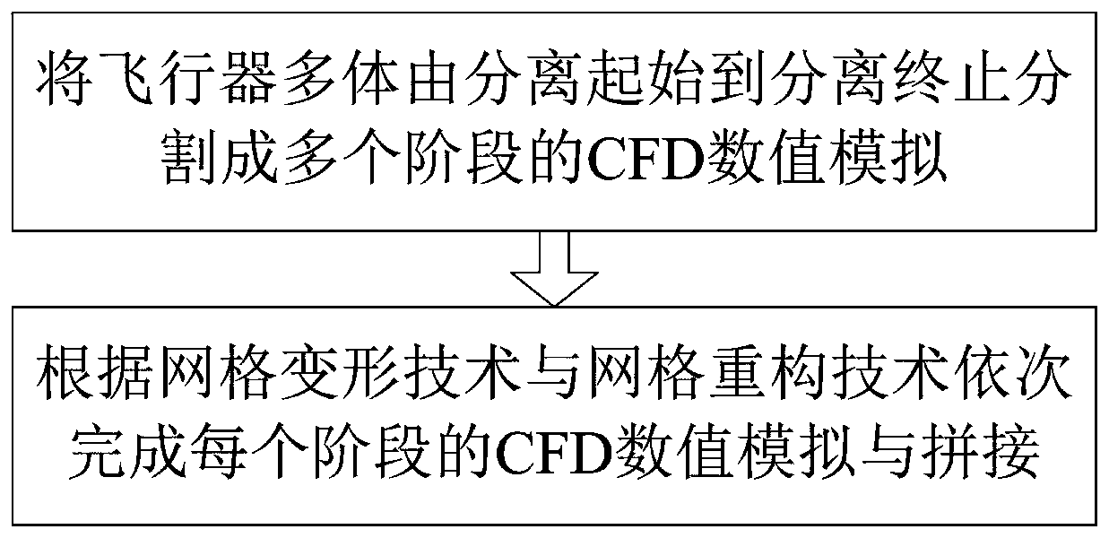
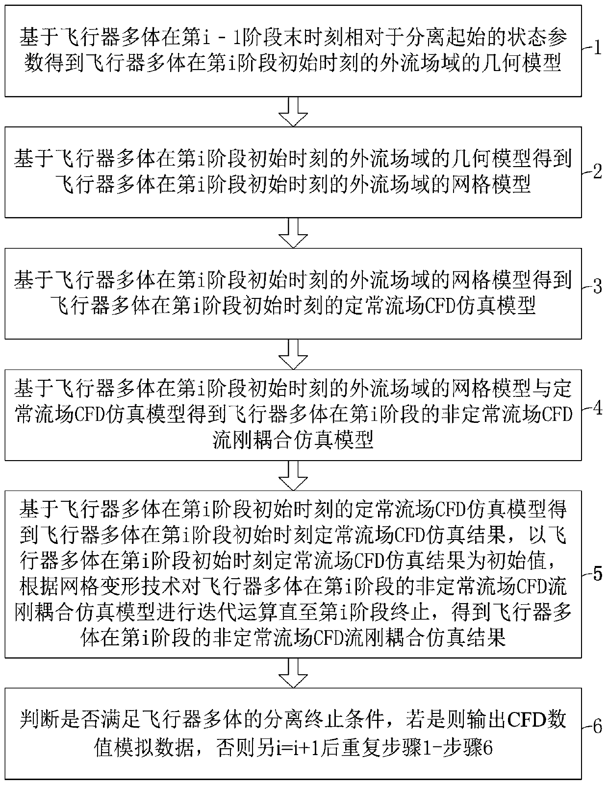
The invention discloses an aircraft multi-body separation CFD simulation method and system based on a hybrid power grid technology. The method comprises the following steps of dividing an aircraft multi-body into the CFD numerical simulation of multiple stages from separation start to separation end; and completing the CFD numerical simulation and splicing of each stage sequentially according toa grid deformation technology and a grid reconstruction technology; and combining a grid deformation technology and a staged grid reconstruction technology. The aircraft multi-body separation CFD numerical simulation method based on the hybrid dynamic grid technology can give full play to the advantages of high calculation efficiency and high calculation precision of thegrid deformation technologyin a small displacement range, also can give full play to the advantage that the staged grid reconstruction technology can effectively improve the grid quality in a staged manner under the conditionof large displacement, and improves the calculation precision, so that the method can be effectively applied to the research on the multi-body separation problem of the unsteady, high-Reynolds-numberand large-displacement aircrafts.

Description

technical field [0001] The invention relates to the field of aircraft multi-body separation simulation, in particular to a CFD simulation method and system for aircraft multi-body separation based on hybrid dynamic grid technology. Background technique [0002] The problem of multi-body separation of aircraft is mostly in the harsh environment of low altitude and high dynamic pressure. Due to the time-varying relative position and relative velocity between multiple bodies, shock wave / shock wave interference, shock wave boundary layer interference, boundary layer separation, and vortex flow will be induced. and other flow phenomena, so that the flow field parameters are in a highly nonlinear and unsteady state, which seriously interferes with the aerodynamic and kinematic characteristics of the aircraft body and separated parts. Many of the above factors directly lead to the multi-body separation process often becoming a high-risk mission action. Therefore, it is necessary t...

Claims


Application Information

Patent Timeline
Patent Type & Authority Applications(China)
IPC IPC(8): G06F17/50G06T17/00
CPCG06T17/00Y02T90/00
Inventor 董杨彪郭叔伟王晶晶夏刚程文科邹小飞刘湘
Owner CHINA POWER IND INTERNET CO LTD
Why Eureka
Try Eureka