

Medical hemostatic clip
A technology of hemostatic clips and clips, applied in medical science, wound clips, surgery, etc., can solve problems such as difficult repeated positioning, delay in operation time, damage to clip performance, etc., and achieve stable and reliable release process, flexible rotation to adjust angle, and release Stable and reliable effect
- Summary
- Abstract
- Description
- Claims
- Application Information
AI Technical Summary
Problems solved by technology
Method used
Image

Examples
Embodiment 1
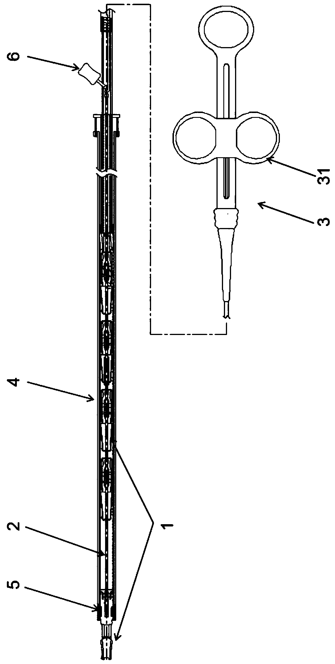
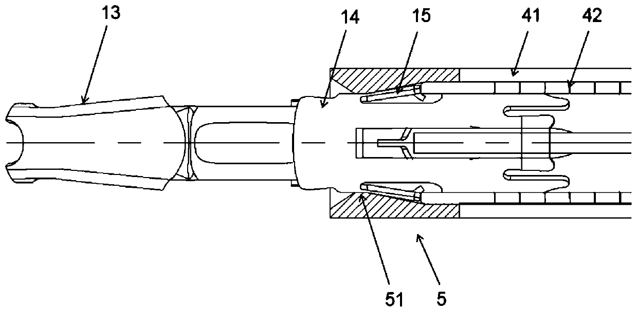
[0063] Such as Figure 1-10 The first embodiment of the shown Chinese medicine hemostatic clip of the present invention, wherein this hemostatic clip is a hair clip (such as figure 1 As shown), there is a clip assembly (not shown in the figure) including more than two clips 1 arranged in the axial direction, and each clip 1 in the clip assembly is connected in series in the axial direction and can control the opening or Closed control line 2, the clip 1 includes a clip body (not shown in the figure) and a clip seat 14, the distal end of the control line 2 is releasably connected to the clip body of the farthest clip 11; The sub also includes a handle 3 located at the proximal end of the control wire 2 and used to control the axial forward and backward movement of the control wire 2, and a sheath 4, the control wire 2 extends along the lumen of the sheath 4, and the control wire 2 The proximal end of the wire is fixedly connected to the slider 31 on the handle 3, and the clip ...
Embodiment 2
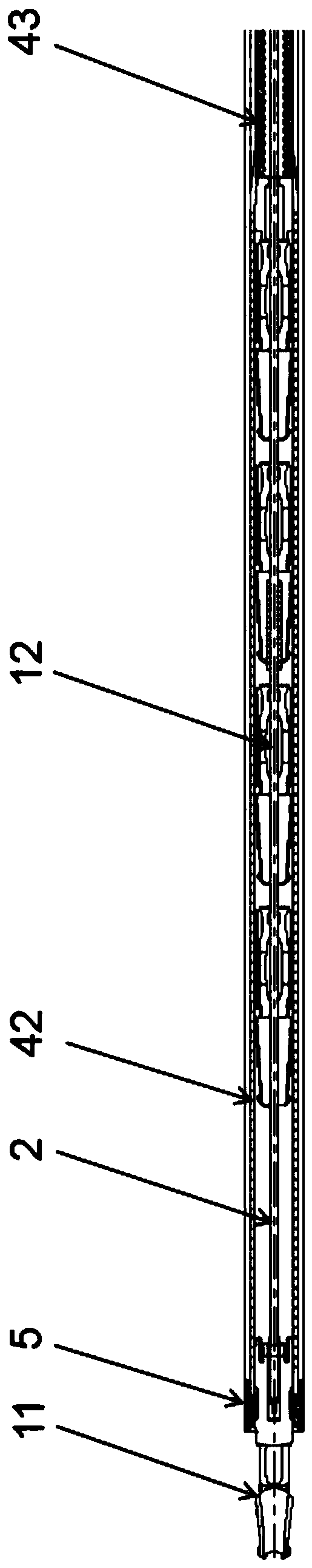
[0079] like Figure 12 As shown, the connection between the outer sheath tube and the inner sheath tube in Example 1 is changed. In Embodiment 2, the proximal end of the outer sheath tube 41 is directly fixedly connected to the outer wall of the second inner sheath tube 43 through the fixed connection part 71. Correspondingly, during the release process, the movement of the control wire can be used alone to control For the release of the most distal clip 11 , the specific operation process can refer to the operation method of releasing the clip by using the control wire in Embodiment 1, and will not be repeated here.
Embodiment 3
[0081] like Figure 13 As shown, based on the basic structure of Embodiment 1, as an alternative, the outer sheath tube 41 and the inner sheath tube in Embodiment 4 are replaced by a relatively movable mode. In the process of releasing the most distal clip 11, the method of moving the outer sheath tube 41 can also be used. Specifically, in the process of releasing the clip, the release assembly is also first released from the release channel of the most distal clip 11, and then along the Figure 13 As shown in the direction of the middle dotted line, by pulling the outer sheath to the proximal end, the protruding surface on the inner side of the limiting boss 51 is radially expanded by the radial and axial pressure of the first inner sheath and then pulled to the farthest point of the first inner sheath. the outer periphery of the end and release the most distal clip 11. It can be seen that, based on Example 1 and Example 3, there are two ways to release the clip in the prese...
PUM
 Abstract
Description
Claims
Application Information