

Polishing device and method for polishing blind hole of non-conductive workpiece
A polishing device, non-conductive technology, used in grinding workpiece supports, grinding/polishing equipment, manufacturing tools, etc., can solve problems such as inability to polish, achieve easy fluid management, fast polishing efficiency, and good flow controllability Effect
- Summary
- Abstract
- Description
- Claims
- Application Information
AI Technical Summary
Problems solved by technology
Method used
Image

Examples
Embodiment Construction
[0047] The present invention will be further described below in conjunction with accompanying drawing:
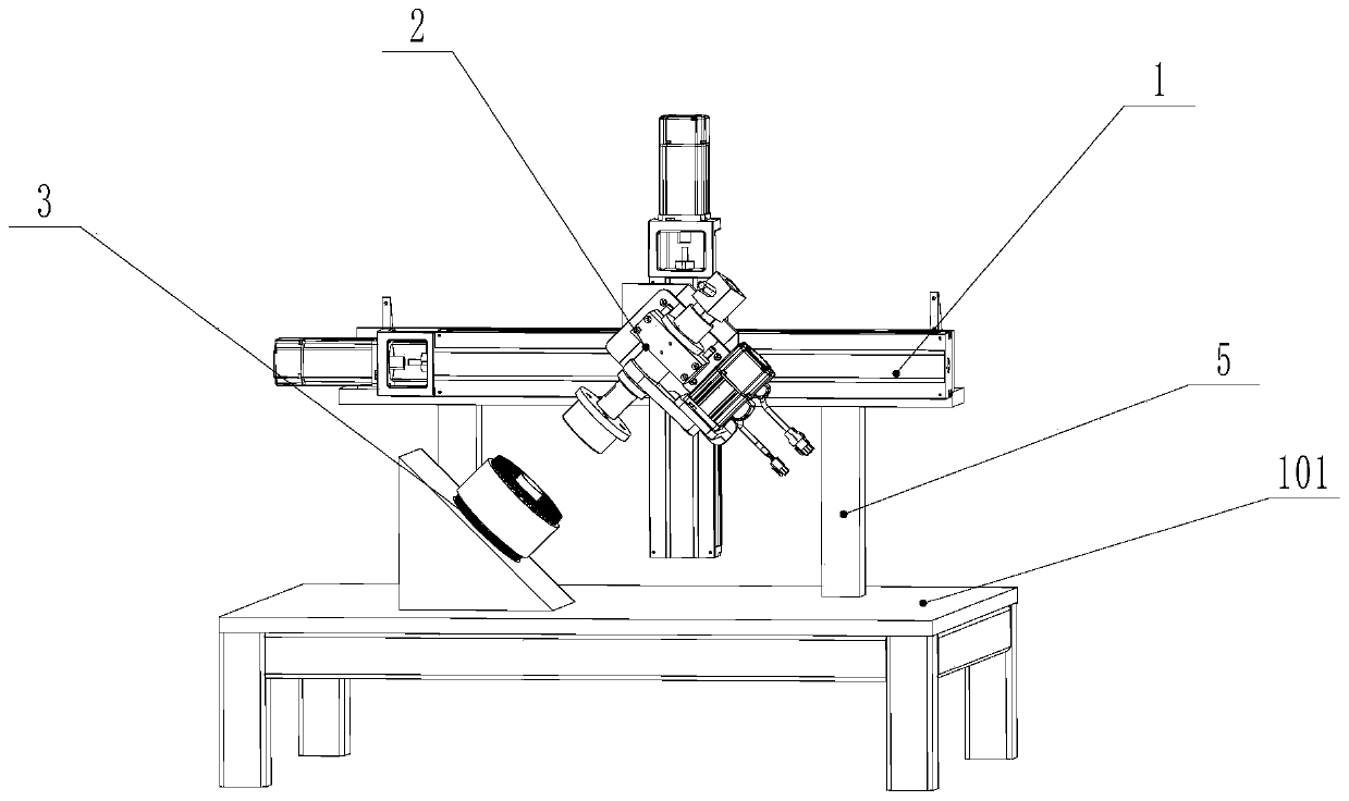
[0048] Such as Figure 1-7 As shown, a polishing device for polishing blind holes of non-conductive workpieces includes a worktable 101, a mobile positioning device 1, a rotating flow channel device 2 and a rotating magnetic field device 3, and the mobile positioning device 1 is installed on the workbench 101. The rotating flow channel device 2 is installed on the mobile positioning device 1, and the rotating magnetic field device 3 is fixed on the workbench 101 obliquely below the rotating flow channel device 2
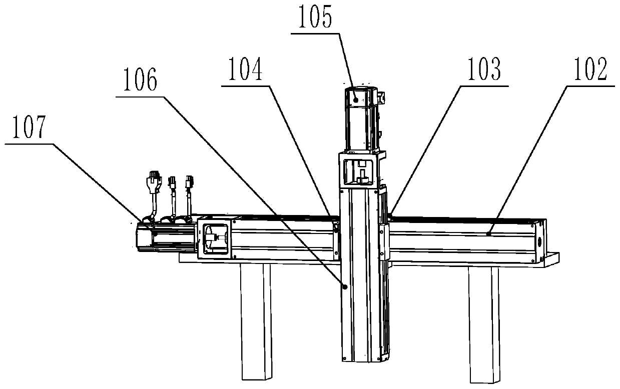
[0049] The mobile positioning device 1 includes a horizontal module mounting frame 5, a horizontal linear module 102, a horizontal module driving motor 107, a vertical linear module 106 and a vertical module driving motor 105, and the horizontal module mounting frame 5 Fixed on the workbench 101; the horizontal linear module 102 is horizontally fixed on the horiz...
PUM
 Abstract
Description
Claims
Application Information