Rotary polishing device and method for blind hole polishing

A polishing device and blind hole technology, which is applied to abrasive feeding devices, grinding/polishing equipment, abrasives, etc., can solve problems such as inability to polish blind holes, and achieve better polishing effect, environmental friendliness, and less pollution.

Pending Publication Date: 2019-12-27
ZHEJIANG UNIV OF TECH
View PDF0 Cites 0 Cited by
  • Summary
  • Abstract
  • Description
  • Claims
  • Application Information

AI Technical Summary

Problems solved by technology

[0004] The purpose of the present invention is to solve the problem that the existing polishing method cannot polish the blind hole printed by 3D printing technology, and proposes a rotary polishing device and method for blind hole polishing, by using periodic positive and negative The pressure makes the abrasive grain flow impact the blind hole of the workpiece, and the blind hole type workpiece can be polished. The blind hole of the workpiece to be processed is in a negative pressure state by pumping air, so that the abrasive grain flow can enter the blind hole more smoothly. During the polishing process In the process, mechanical rotation and abrasive flow are used to repeatedly impact the blind hole of the workpiece, and the blind hole of the workpiece to be processed is subjected to micro-cutting and polishing

Method used


Image

  • Rotary polishing device and method for blind hole polishing
  • Rotary polishing device and method for blind hole polishing
  • Rotary polishing device and method for blind hole polishing

Examples


Embodiment Construction

[0047] The present invention will be further described below in conjunction with the accompanying drawings:

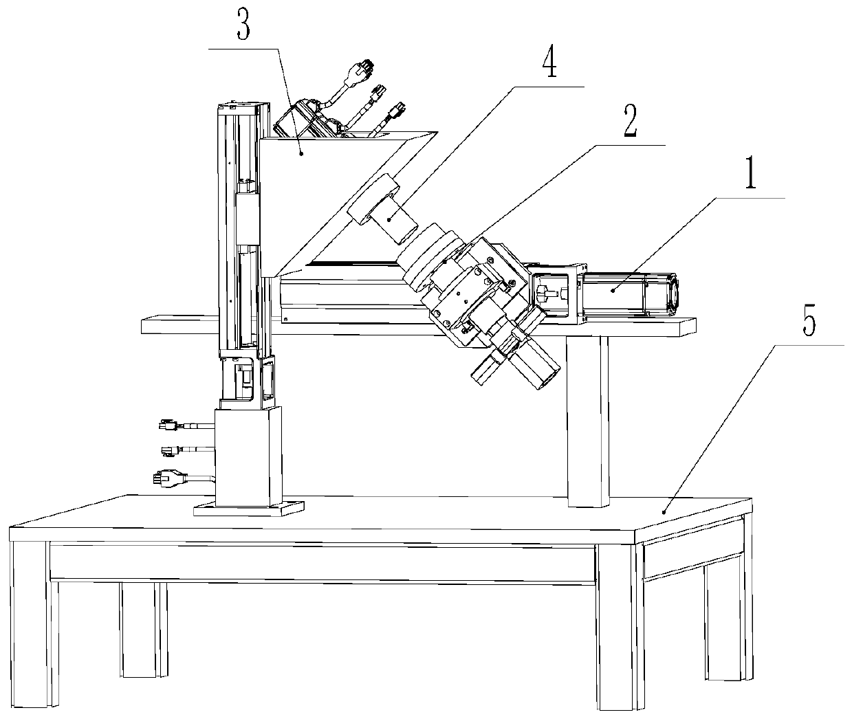
[0048] like Figures 1 to 8 As shown, a rotary polishing device for blind hole polishing includes a worktable 5 , a moving positioning assembly 1 , a flow channel assembly 2 and a rotating clamping assembly 3 .

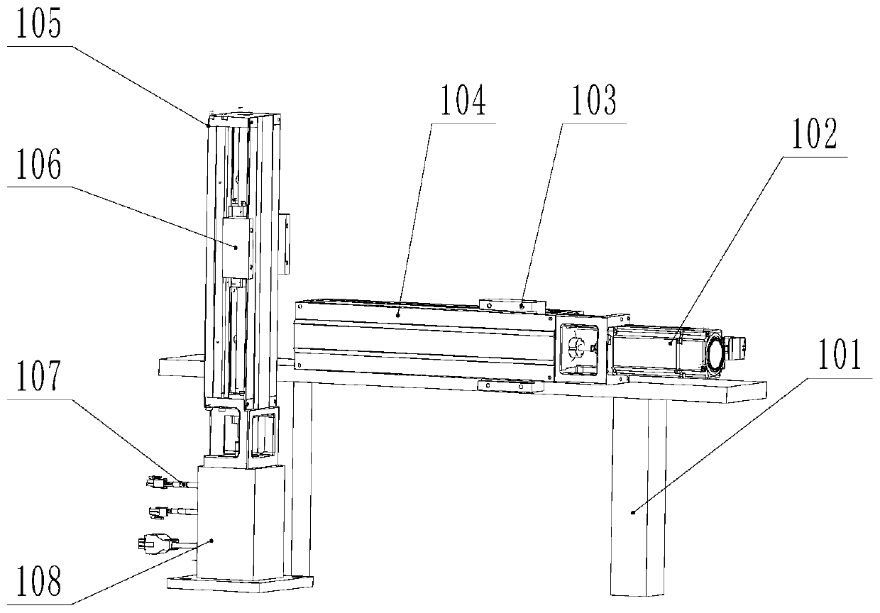
[0049] The mobile positioning assembly 1 includes a horizontal module mounting frame 101, a horizontal linear module 104, a horizontal module driving motor 102, a vertical linear module 105 and a vertical module driving motor 107. The horizontal module mounting frame 101 Fixed on the workbench 5; the horizontal linear module 104 is horizontally fixed on the horizontal module mounting frame 101, the horizontal module driving motor 102 is fixed on one end of the horizontal linear module 104, and the horizontal module driving motor 102 The drive shaft is connected to the horizontal linear module 104 and drives the horizontal slider 103 on the horizontal linear m...


PUM


Abstract

The invention discloses a rotary polishing device and method for blind hole polishing. The rotary polishing device comprises a workbench, a movable positioning assembly, a flow pass assembly and a rotary clamping assembly. The movable positioning assembly comprises a horizontal module mounting rack, a horizontal straight line module, a horizontal module driving motor, a vertical straight line module and a vertical module driving motor. The rotary clamping assembly comprises a rotary motor, a motor mounting base, a bearing, a supporting block, an auxiliary clamping head and a vertical mountingbase. The flow pass assembly comprises a main clamping head, a rotary joint fixing base, a flow pass fixing plate, a sliding rail connecting plate, an extraction opening check valve, a gas-liquid abrasive particle flow joint, an abrasive particle flow inlet valve, an air pressure opening check valve, a flow pass joint, a flange-type rotating joint and a main clamping end O ring. By adoption of therotary polishing device and method for blind hole polishing, blind holes of blind hole type workpieces can be polished, the rotary motor can be used for driving the workpieces to be machined to rotate in the machining process, abrasive particle flow can impact the inner walls of the blind holes in a more unordered mode during machining, and machining efficiency of the blind holes is improved.

Description

technical field [0001] The present invention relates to the field of abrasive flow polishing, more particularly, to a rotary polishing device and method for blind hole polishing, which utilizes periodic positive and negative pressures to make abrasive flow impact a rotating workpiece. Background technique [0002] 3D printing technology is also called additive manufacturing technology, which is an advanced manufacturing technology called rapid prototyping in China. The manufacture of three-dimensional solids is transformed into the accumulation of two-dimensional layers and the continuous superposition along the forming direction, and finally the manufacture of three-dimensional solids is realized. With the increasing use of 3D printing technology, more and more blind hole products are produced using 3D printing technology. Compared with through holes, blind holes refer to non-penetrating holes, which are widely used in daily life and industrial production. At the same time...

Claims


Application Information

Patent Timeline
Patent Type & Authority Applications(China)
IPC IPC(8): B24C1/08B24C3/32B24C5/00B24C7/00
CPCB24C1/08B24C3/325B24C5/00B24C7/0046
Inventor 单晓杭汪佳成张利李研彪叶必卿
Owner ZHEJIANG UNIV OF TECH
Why Eureka
Try Eureka